SERVICE PROCEDURES 47
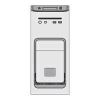
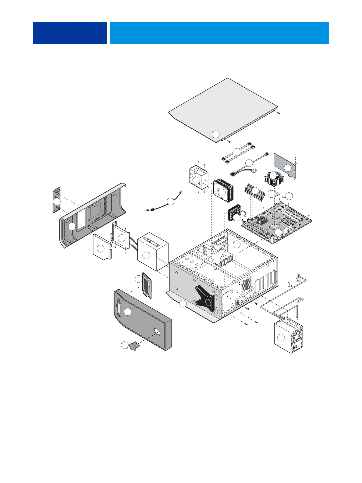
FIGURE 13: Exploded view of imagePRESS Server components
21
1
12
13
8
10
15
17
16
5
22
23
14
7
3
2
4
6
9
11
18
19
20
24
i
Key
1. Top panel plug
2. Top panel
3. User Interface Board (UIB)
4. Component sled
5. Switch bank assembly
6. DVD drive
7. Front panel
8. Upper faceplate
9. UIB cable
10. HDD bracket
11. HDDs
12. Side panel (left)
13. HDD data cables
14. DVD drive power/data combination cable
15. CPU cooling assembly
16. Copier interface board
17. DIMMs
18. CPU
19. Battery
20. Motherboard
21. Fan
22. Chassis
23. Power supply
24. Side panel (right)
NOTE: UIB buttons, CPU fan cable, tie-wraps, cable clamps, dongle(s), or external cables are not shown.