LIST OF FIGURES 8
FIGURE 21: Removing/replacing the UIB buttons 60
FIGURE 22: Diagram of the imagePRESS Server motherboard 62
FIGURE 23: Removing the motherboard 64
FIGURE 24: Connecting the dongle 71
FIGURE 25: Motherboard DIMM sockets 77
FIGURE 26: Releasing a DIMM 78
FIGURE 27: CPU cooling assembly 79
FIGURE 28: Removing/replacing the CPU 81
FIGURE 29: Inspecting the cooling assembly pins on underside of motherboard 83
FIGURE 30: Motherboard battery 84
FIGURE 31: Removing the fan 86
FIGURE 32: Removing/replacing the power supply 89
FIGURE 33: imagePRESS Server HDDs 92
FIGURE 34: Removing/replacing the HDD bracket 93
FIGURE 35: Removing/replacing the HDDs from the HDD bracket 94
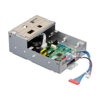
FIGURE 36: Component Sled with switch bank assembly 97
FIGURE 37: Removing/replacing the Component Sled from the chassis 98
FIGURE 38: Removing/replacing the switch bank assembly 99
FIGURE 39: imagePRESS Server DVD drive 101
FIGURE 40: Removing/replacing the DVD drive 102
FIGURE 41: Troubleshooting the system 110
FIGURE 42: imagePRESS Server external cable connections 112
FIGURE 43: Normal startup sequence 119
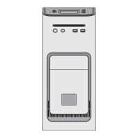
FIGURE 44: imagePRESS Server installed on the furniture 137