© Cesab 13 – 4 T Code(s): 841, 842, 843
Repair manual: Tiller arm 4000 Model(s): S210, S212, S212S, S212L, S214, S214L, S220D
Publication Number: 7588857-040 Date: 2018-05-01 Applies from serial number: 6384351-
13.4 Replacing the safety sensor
13.4.1 Removal
1. Remove the gas strut. See section “13.3 Replacing an gas strut”.
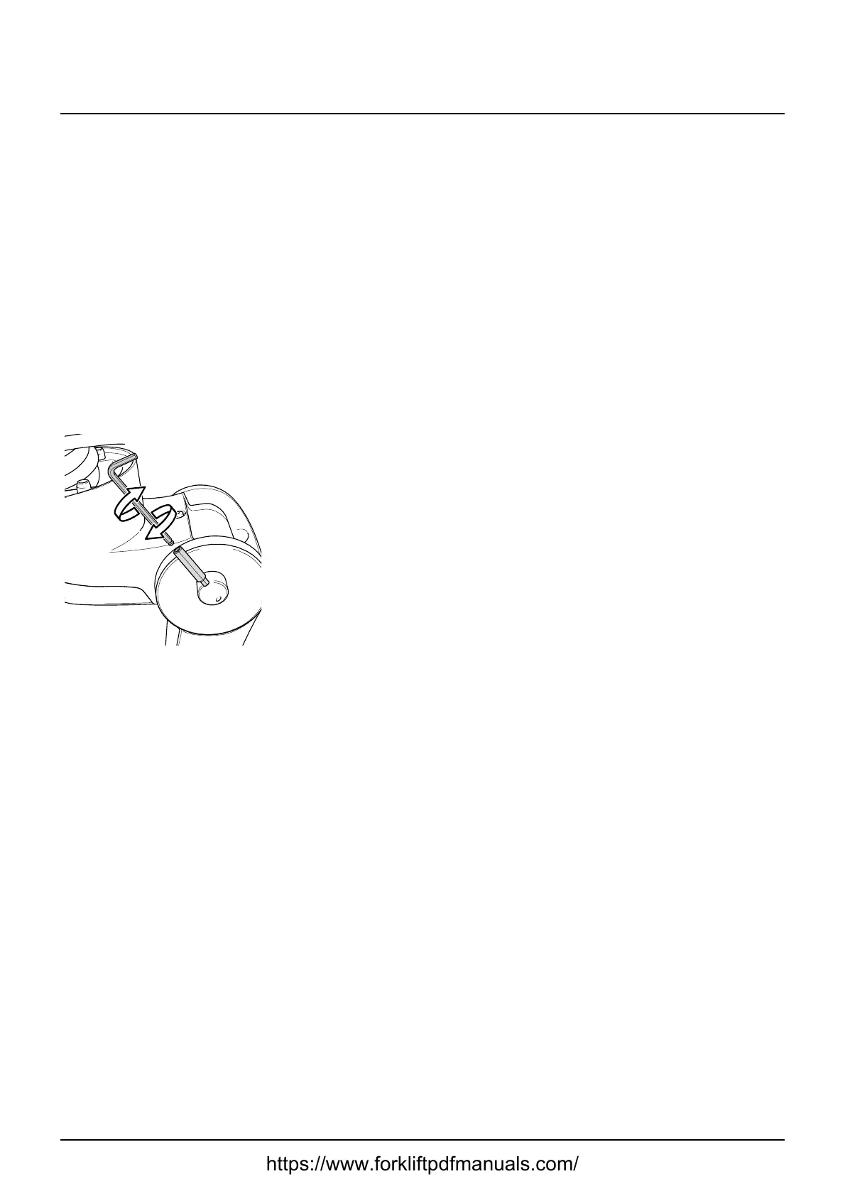
2. Unscrew the stop screw (I) of the shaft (L). See figure.
3. Turn the shaft (L) until the back of the indicator sleeve (M) becomes
accessible.
4. Loosen the indicator sleeve (L).
To prevent damage to the sleeve, pry the indicator sleeve loose from both
sides at the same time.
5. Tap out the shaft (L).
Note:
Make sure that the handle does not drop down and damage the cables.
6. Remove the cable clamp retaining screw (W).
7. Remove the sensor retaining screw (S).
8. Detach contact B60 from the sensor (K).
9. Remove the sensor.
13.4.2 Installation
1. Fit the sensor (K)
2. Attach connector B60 to the sensor.
3. Apply Loctite to the sensor retaining screw (S) or replace it. Fasten the
screw.
4. Fasten the cable clamp retaining screw (W).
Note:
The cable must be routed to the right of the sensor (K), towards the spring
pin.
5. Screw the stop screw (I) into the shaft (L). See figure.
6. Install the gas spring See section “13.3 Replacing an gas strut”.
7. Check for correct operation of the safety sensor.
https://www.forkliftpdfmanuals.com/