© Cesab 20 – 5 T Code(s): 841, 842, 843
Repair manual: Electrical components and wiring diagrams Model(s): S210, S212, S212S, S212L, S214, S214L,
S220D
Publication Number: 7588857-040 Date: 2018-05-01 Applies from serial number: 6384351-
20.2 Wiring diagram
20.2.1 List of symbols
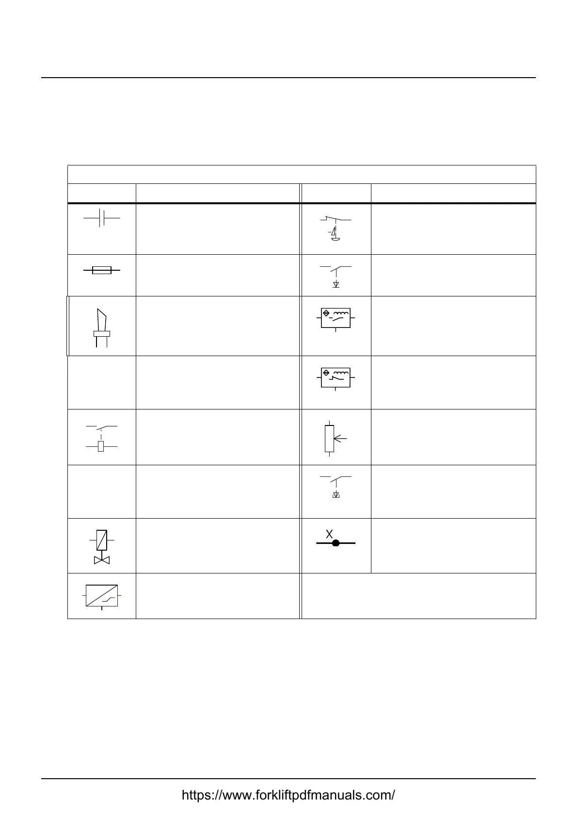
Table 1: List of symbols
Symbol Description Symbol Description
Truck battery. Emergency switch off NC
Fuse Switch, pressure (weight) oper-
ated
Horn Sensor, inductive NO
Motor, AC
1
1. AC = Alternating Current
Sensor, inductive NC
Contactor Variable resistance (potentiome-
ter)
Brake coil (normally applied) Push switch NO
Coil for the hydraulic solenoid
valve
Multi-pin connector
Pressure sensor, analogue NO = Normally open
NC = Normally closed
https://www.forkliftpdfmanuals.com/