CS35 2013.04
3.1.13-101 3.1.13-101Electronic Control System - ME7
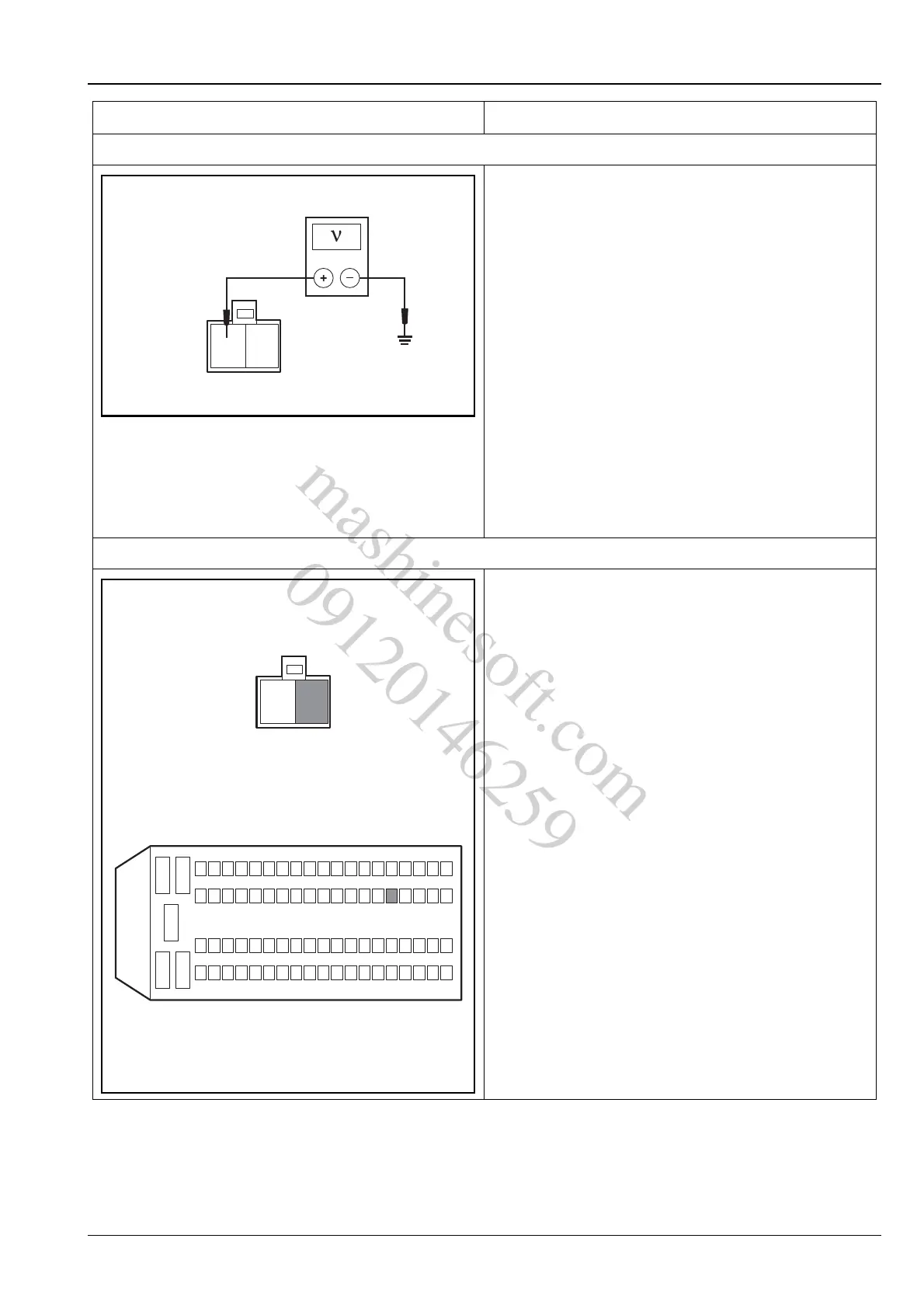
2. Inspect the power supply line of intake control valve
A. Turn the ignition switch to position "LOCK".
B. Disconnect camshaft phase sensor wiring harness
connector E02.
C. Turn the ignition switch to position "ON".
D. Measure the voltage between terminal 2 of intake
control valve wiring harness connector E02 and
reliable grounding.
Standard Voltage Value: 11 ~ 14 V
Is the voltage normal?
Y
Go to step 3.
N
Repair the circuit faults from terminal 2 of camshaft
position sensor wiring harness connector E02 to the
terminal 45 of the engine compartment electric cen-
ter C10 fuse EF23.
3. Inspect the ground circuit of the intake control valve
A. Turn the ignition switch to position "LOCK".
B. Disconnect the battery negative cable.
C. Disconnect OCV intake control valve wiring harness
connector E02.
D. Disconnect ECM wiring harness connector E01.
E. Measure the resistance between terminal 1 of OCV
intake control valve wiring harness connector E02
and terminal 48 of ECM wiring harness connector
E01.
Standard Resistance Value: less than 5 Ω
Is the resistance normal?
Y
Go to step 4.
N
Repair the circuit between the terminal 1 of OCV
intake control valve wiring harness connector E02
and the terminal 48 of ECM wiring harness connec-
tor E01.
Test Conditions Details/Results/Actions
E01
E02
21
12
3
45
624
2543
44
48
62
6381
A3113165
mashinesoft.com
09120146259