3.1.13-116
CS35 2013.04
3.1.13-116Electronic Control System - ME7
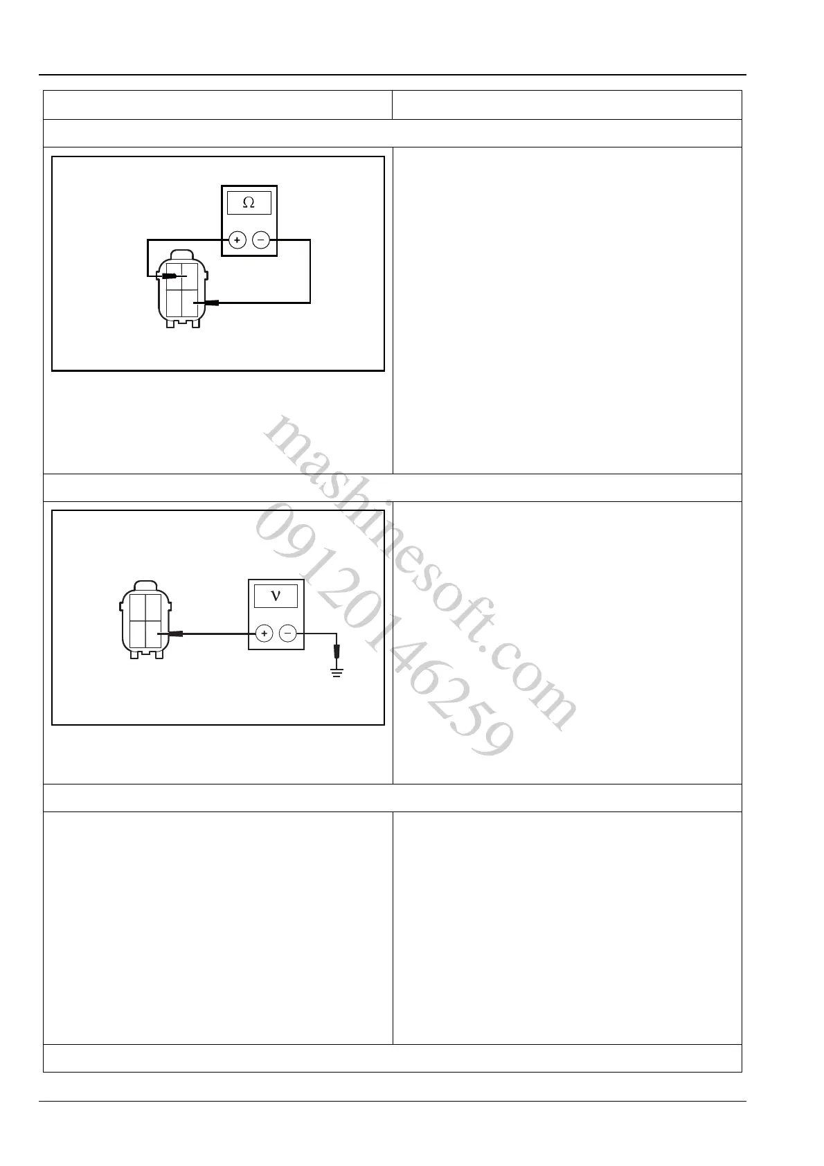
2. Inspect the post - catalytic oxygen sensor heater resistance value
A. Turn the ignition switch to "LOCK" position.
B. Disconnect the post - catalytic oxygen sensor wiring
harness connector E08.
C. Measure the resistance value of the heater that
between terminal 2 and terminal 4 of post - catalytic
oxygen sensor wiring harness connector E08.
Standard Resistance Value: 20 ℃ (68ºF) 1 ~ 6 Ω
Is the resistance value normal?
Y
Go to step 3.
N
Replace the post - catalytic oxygen sensor.
Refer to: Post - Catalytic Oxygen Sensor
(3.1.13 Electronic Control System - ME7,
Removal and Installation).
3. Inspect the heater working voltage
A. Turn the ignition switch to position "LOCK".
B. Disconnect the post - catalytic oxygen sensor wiring
harness connector E08.
C. Turn the ignition switch to position "ON".
D. Measure the voltage between the terminal 4 of post
- catalytic oxygen sensor wiring harness connector
E08 and the reliable grounding.
Standard Voltage Value: 11 ~ 14 V
Is voltage normal?
Y
Go to step 5.
N
Go to step 4.
4. Inspect the heater power supply circuit
A. Remove the fuse EF23 of the eengine compartment
fuse and relay box C01.
B. Inspect the fuse.
Is the fuse normal?
Y
Repair the circuit from terminal 4 of post - catalytic
oxygen sensor wiring harness connector E08 to ter-
minal 45 of the engine compartment electric center
C10 ER23.
N
Replace the fuse.
5. Inspect the heater control signal circuit
Test Conditions Details/Results/Actions
mashinesoft.com
09120146259