CS35 2013.04
3.1.12-9 3.1.12-9Engine Immobilizer System
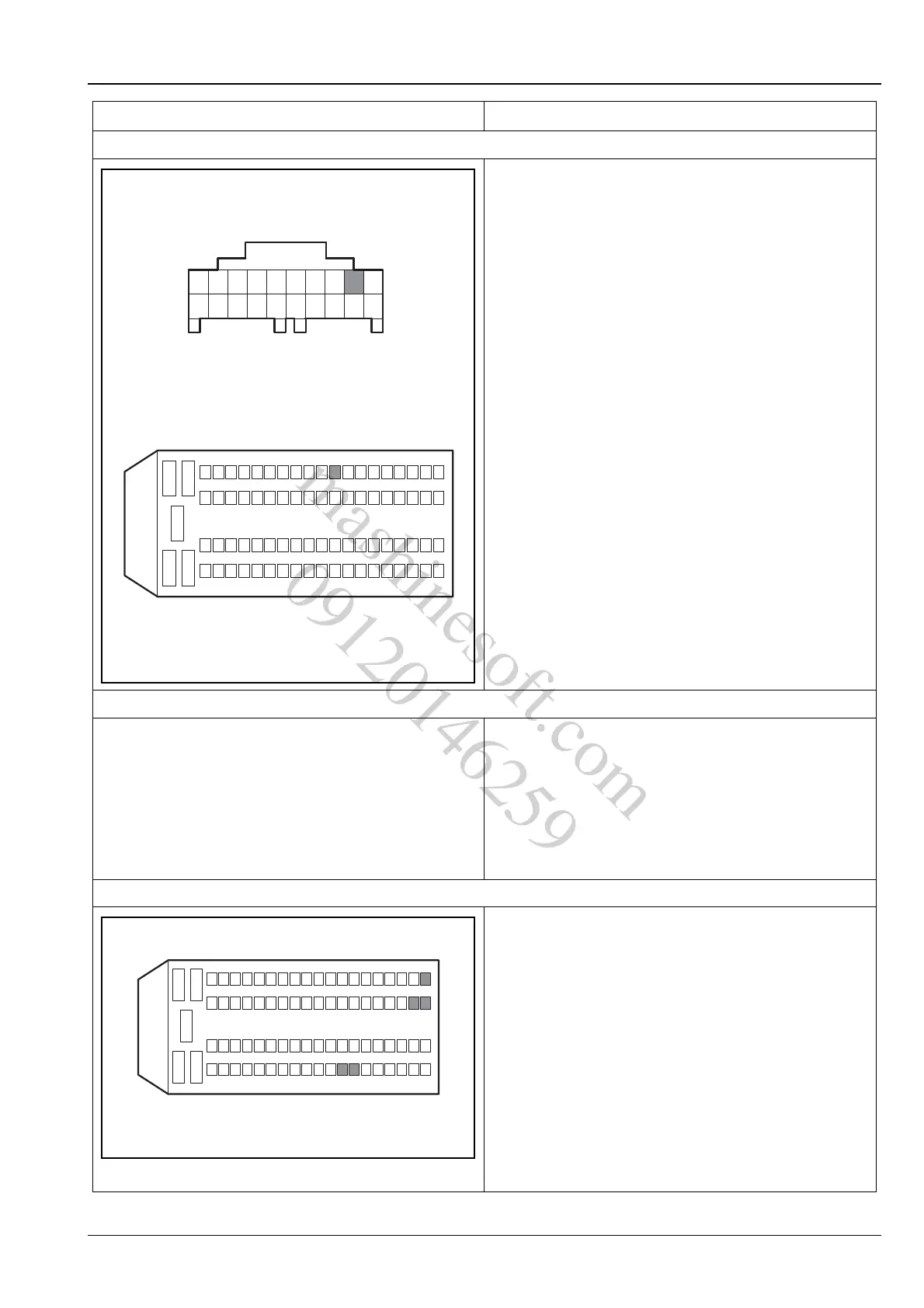
5. Inspect the K-line network cable between ECM and BCM
A.Turn the ignition switch to position "LOCK".
B.Disconnect the battery negative cable.
C.Disconnect the wiring harness connector P24 of the
body control module and the ECM wiring harness
connector E01.
D.Measure with multimeter the resistance between the
terminal 2 of BCM wiring harness connector P24
and the terminal 71 of the ECM wiring harness
connector E01.
Standard Resistance Value: less than 5 Ω
Is the resistance value normal?
Y
Go to step 6.
N
Repair the open circuit terminal 2 of BCM wiring
harness connector P24 and terminal 71 of the ECM
wiring harness connector E01.
6. Replace the password transponder
A.Replace the password transponder of the remote
key, and rematch the key.
Is the system normal?
Y
Verify the system is normal.
N
Go to step 7.
7. Inspect the ECM power supply circuit
A.Turn the ignition switch to position "LOCK".
B.Measure from the back of ECM wiring harness
connector E01.
C.Turn the ignition switch to "ON" position and use a
multimeter to measure the voltage between the
terminal 12, 13, 44, 45 and 63 of the ECM wiring
harness connector E01 and the power supply.
Standard Voltage Value: 11 ~ 14 V
Is the voltage normal?
Y
Go to step 8.
N
Repair and inspect the ECM power supply circuit.
Test conditions Details/Results/Actions
P24
10 1
20
2
11
E01
12
3
45
624
25
71
43
4462
6381
A3112014
12
3
45
624
2543
4462
63
13
12
45
81
E01
A3113031
mashinesoft.com
09120146259