3.1.13-66
CS35 2013.04
3.1.13-66Electronic Control System - ME7
MIL Indicator Fault Diagnosis
Test Conditions Details/Results/Actions
1. Inspect the instrument for other indicator state
A. Turn the ignition switch to position "ON".
B. Inspect the state of all the instrument warning
lamps.
Is there any other warning light is abnormal on
besides MIL fault indicator?
Y
Go to step 2.
N
Go to step 4.
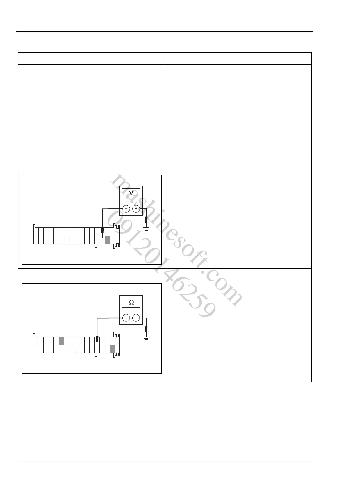
2.Inspect the instrument power supply circuit
A. Turn ignition switch to "ON " position, with a
multimeter inspect the power supply circuit of
instrument cluster harness connector P07 terminal
4 and 15.
Standard Voltage Value: 11 ~ 14 V
Is the voltage normal?
Y
Go to step 3.
N
Repair the instrument cluster power supply circuit.
3. Inspect the ground circuit of the instruments
A. Turn ignition switch to "LOCK" position, use a
multimeter to inspect ground circuit of the terminal
13, 16 and 22 of the instrument cluster harness
wiring connector P11.
Standard Resistance Value: less than 5 Ω
Is the resistance value normal?
Y
Go to step 4.
N
Repair the instrument cluster ground circuit.
11614 15
17 32
P11
A3113110
mashinesoft.com
09120146259