3.1.12-8
CS35 2013.04
3.1.12-8Engine Immobilizer System
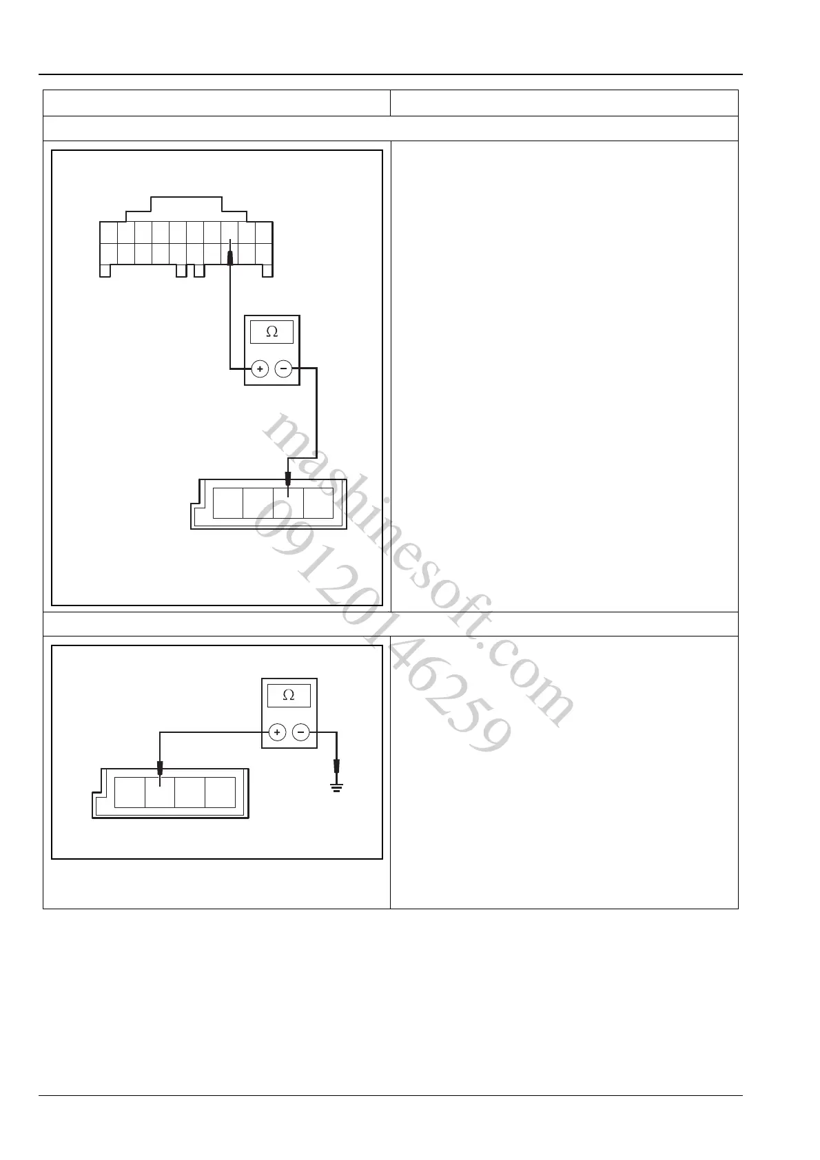
3. Inspect the Lin network circuit of the immobilizer controller
A.Turn the ignition switch to position "LOCK".
B.Disconnect the battery negative cable.
C.Disconnect the wiring harness connector P24 of the
body control module and the wiring harness
connector P10 of the immobilizer controller.
D.Measure the resistance value between the terminal
3 of the BCM wiring harness connector P24 and the
terminal 3 of the immobilizer controller wiring
harness connector P10 with a multimeter.
Standard Resistance Value: less than 5 Ω
Is the resistance value normal?
Y
Go to step 4.
N
Inspect and repair the open circuit between the ter-
minal 3 of the BCM wiring harness connector P24
and the terminal 3 of the immobilizer controller wir-
ing harness connector P10.
4.Inspect the immobilizer controller ground circuit
A.Turn the ignition switch to position "LOCK".
B.Disconnect the body control module wiring harness
connector P10.
C.Measure the resistance between terminal 2 of
immobilizer controller wiring harness connector P10
and reliable ground with the multimeter.
Standard Resistance Value: less than 5 Ω
Is the resistance value normal?
Y
Go to step 5.
N
Inspect and repair the ground circuit of the immobi-
lizer controller.
Test conditions Details/Results/Actions
P24
10 1
20
3
11
P10
134
A3112011
mashinesoft.com
09120146259