3.1.12-12
CS35 2013.04
3.1.12-12Engine Immobilizer System
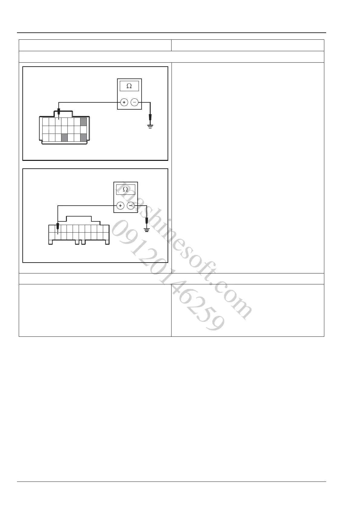
11. Inspect the BCM ground circuit
A.Turn the ignition switch to position "LOCK".
B.Disconnect the battery negative cable.
C.Disconnect the body control module wiring harness
connector P14, P25.
D.Measure the resistance between terminal 1, 3, 12
and 13 of the BCM wiring harness connector P14
and terminal 19 of P25 and the reliable ground.
Standard Resistance Value: less than 5 Ω
Is the resistance value normal?
Y
Go to step 12.
N
Inspect and repair the BCM ground circuit.
12.Replace the BCM
A.Replace the BCM.
Refer to: Body Control Module (4.3.14
Body Control System, Removal and Instal-
lation).
Confirm the repair is finished.
Test conditions Details/Results/Actions
P14
1
2
3
4
6
7
9
10
12
13
15
16
18
19
21
A3112008
mashinesoft.com
09120146259