CS35 2013.04
3.1.13-143 3.1.13-143Electronic Control System - ME7
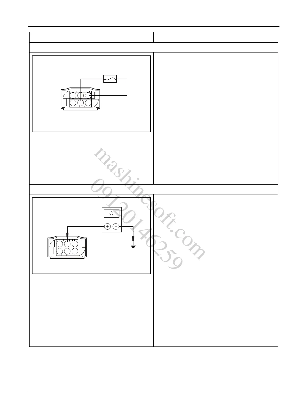
4. Inspect the throttle position sensor signal circuit
A. Turn the ignition switch to position "LOCK".
B. Disconnect the throttle position sensor wiring
harness connector E23.
C. Turn the ignition switch to position "ON".
D. Connect a jumper wire with a 5A fuse between
terminals 3 and 5 of E23, use diagnostic tool to
observe the "actual throttle position sensor voltage"
parameter.
Standard Voltage Value: 4.5 ~ 5.5 V
E. Connect the throttle position sensor wiring harness
connector E23.
Is the voltage normal?
Y
Go to step 5.
N
Repair the fault circuit between terminal 5 of throttle
position sensor wiring harness connector E23 and
terminal 38 of ECM wiring harness connector E01.
5. Inspect the throttle position sensor grounding
A. Turn the ignition switch to position "LOCK".
B. Disconnect the throttle position sensor wiring
harness connector E23 and measure the resistance
between terminal 2 of the throttle position sensor
wiring harness connector E23 and reliable
grounding.
Standard Resistance Value: 10 MΩ or more
C. The ignition switch is set to position "ON".
D. Measure the resistance between the terminal 2 of
throttle position sensor wiring harness connector
E23 and the reliable grounding.
Standard Resistance Value: less than 5 Ω
E. Connect the throttle position sensor wiring harness
connector E23.
Is the resistance value normal?
Y
Go to step 6.
N
Repair the fault circuit between terminal 2 of throttle
position sensor wiring harness connector E23 and
terminal 78 of ECM wiring harness connector E01.
Test Conditions Details/Results/Actions
mashinesoft.com
09120146259