3.1.13-190
CS35 2013.04
3.1.13-190Electronic Control System - ME7
3. Diagnosis Procedures
Test Conditions Details/Results/Actions
1. General inspection
A. Inspect the wiring harness connector E19 of intake
camshaft position sensor for loose or poor contact.
B. Inspect the intake camshaft position sensor for
proper installation.
C. Inspect the intake camshaft position sensor for
normal clearance.
Is it normal?
Y
Go to step 2.
N
Repair the fault.
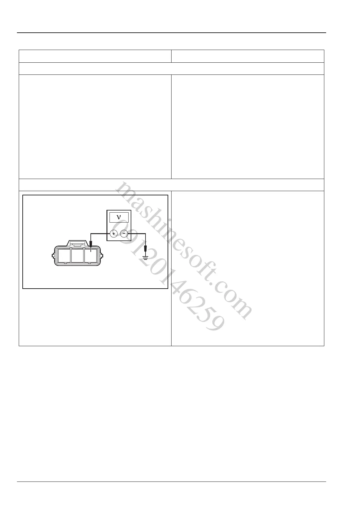
2. Inspect the intake camshaft position sensor power supply circuit
A. Turn the ignition switch to "LOCK" position.
B. Disconnect the battery negative cable.
C. Disconnect the wiring harness connector E19 of
intake camshaft position sensor.
D. Turn the ignition switch to position "ON".
E. Measure the voltage between terminal 3 of intake
camshaft position sensor wiring harness connector
E19 and reliable grounding.
Standard Voltage Value: 4.5 ~ 5.5 V
Is the voltage normal?
Y
Go to step 4.
N
Repair the circuit faults between the terminal 3 of
intake camshaft position sensor wiring harness con-
nector E19 and the terminal 32 of ECM wiring har-
ness connector E01.
mashinesoft.com
09120146259