3.1.13-248
CS35 2013.04
3.1.13-248Electronic Control System - ME7
2. Eliminate the DTC
A. Connect the diagnostic tool.
B. Use a diagnostic tool to delete DTC.
C. Swing, pull and press the diagnosis joint DLC, engine
control module (ECM) and vehicle body control
module (BCM) wiring harness connector.
D. Use the diagnostic tool to redo the diagnosis for
DTC.
Is there DTC U0001, U0101, U0140 ?
Y
Go to step 3.
N
Intermittent fault.
Refer to: Intermittent Fault Diagnosis
(3.1.13 Electrical Control System - ME7,
Symptom Diagnosis and Testing).
3. Inspect and repair the CAN bus circuit
A. Inspect and repair the CAN bus circuit.
Refer to: CAN Bus Integrity Inspection
(4.3.15 On-board Network System, Descrip-
tion and Operation).
Is the network normal?
Y
Go to step 4.
N
Inspect and repair the CAN network circuit of each
control module, and replace the failed modules.
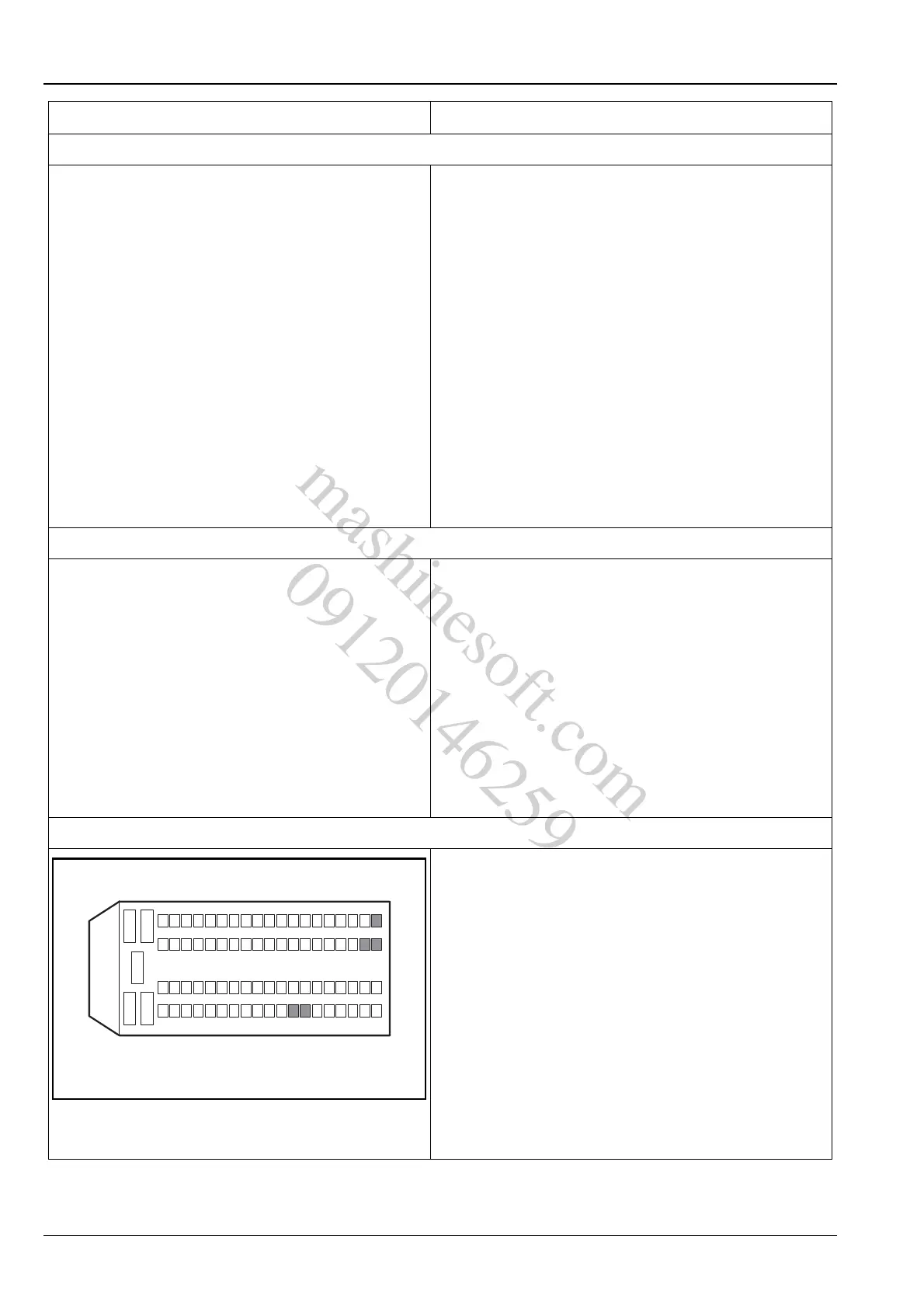
4. Inspect the ECM power supply circuit
A. Turn the ignition switch to position "LOCK".
B. Measure from the back of ECM wiring harness
connector E01.
C. Turn the ignition switch to "ON" position and use a
multimeter to measure the voltage between the
terminals 12, 13, 44, 45 and 63 of the ECM wiring
harness connector E01 and the power supply.
Standard Voltage Value: 11 ~ 14 V
Is the voltage normal?
Y
Go to step 5.
N
Repair and inspect the ECM power supply circuit.
Test Conditions Details/Results/Actions
12
3
45
624
2543
4462
63
13
12
45
81
E01
A3113031
mashinesoft.com
09120146259