CS35 2013.04
3.1.13-39 3.1.13-39Electronic Control System - ME7
4. Inspect the engine module A/C on signal
A. Turn the ignition switch to "ON" position.
B. Measure the level signal of connecting wire of
terminal 75 of engine control module wiring harness
connector E01 with a multimeter, while A/C is on.
When A/C is turned on, whether the voltage of ter-
minal 75 of E01 is 0 V ?
Y
Go to step 5.
N
Repair the circuit.
5. Inspect the fuel injector
A. Remove the fuel injector.
B. Use fuel Injector dedicated cleaning analyzer
inspects the fuel injector for leakage, blockages or
the phenomenon of flow out of tolerance.
Is the fuel injector normal?
Y
Go to step 6.
N
Replace the fuel injector.
Refer to: Fuel Injector (3.1.13 Electronic
Control System - ME7, Removal and
Installation).
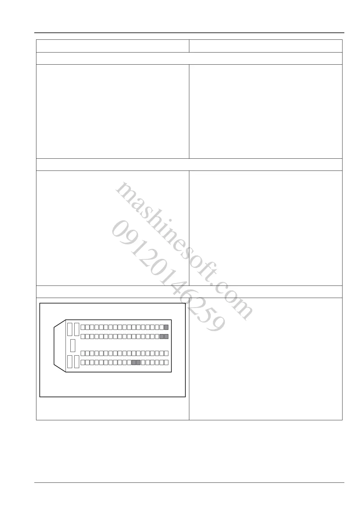
6. Inspect the ECM power supply circuit
A.Turn the ignition switch to position "LOCK".
B.Measure from the back of ECM wiring harness
connector E01.
C.Turn the ignition switch to "ON" position and use a
multimeter to measure the voltage between the
terminals 12, 13, 44, 45 and 63 of the ECM wiring
harness connector E01 and the power supply.
Standard Voltage Value: 11 ~ 14 V
Is the voltage normal?
Y
Go to step 7.
N
Repair and inspect the ECM power supply circuit.
Test Conditions Details/Results/Actions
12
3
45
624
2543
4462
63
13
12
45
81
E01
A3113031
mashinesoft.com
09120146259