CHK Power Quality Pty Ltd, User Manual – Miro Power Quality Logger and Analyser, 15 August 2016
Website: www.chkpowerquality.com.au; Enquiries: sales@chkpowerquality.com.au; Page 25
Address: Unit 1, 3 Tollis Place, Seven Hills, NSW 2147, Sydney, Australia; ABN: 53 169 840 831; Telephone: +61 2 8283 6945;
Fax: +61 2 8212 8105; Website: www.chkpowerquality.com.au
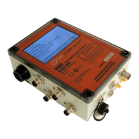
Connect using an IP address
Use this only for WiFi, Cellular or Ethernet communications.
Click the ’Connect TCP/IP’ button shown in figure 5.2.3. A box with a default IP address will
appear as shown in figure 5.2.10. Alter the address as required and click the ’Ok’ button.
The message box shown in figure 5.2.11 will appear if the device could not connect. If
connection is established then the ‘Miro Operations’ window shown in figure 5.2.9 will
appear.
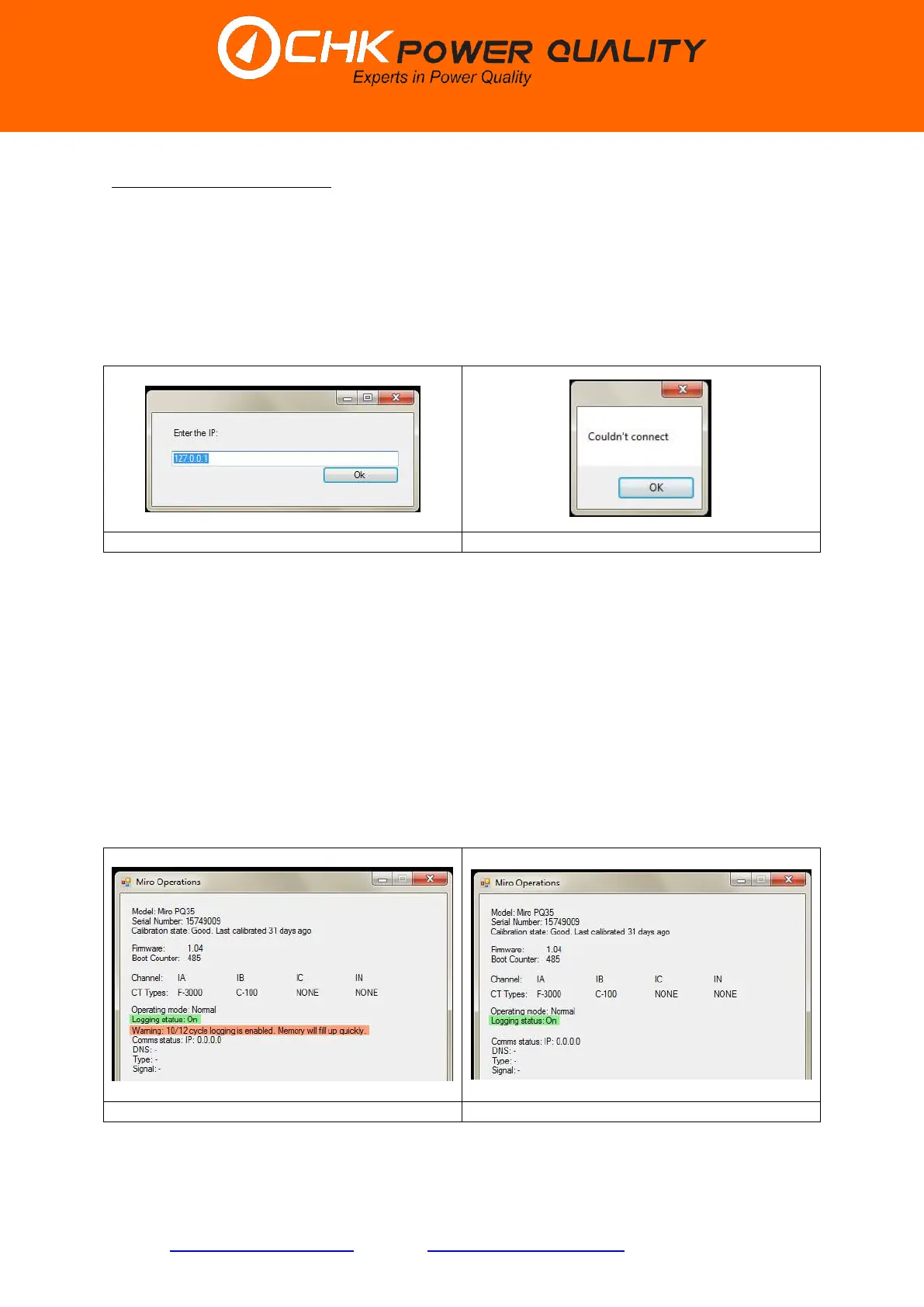
Calibration state
Normally the calibration state of the Miro is ‘Good’, indicating that the Miro is fit for service. If
for some reason the Miro is not fit for service then the calibration state will change to ‘Bad’.
If ‘Last calibrated’ exceeds 365 days then the calibration state will change to ‘Due’, indicating
that the Miro should be returned for calibration. If ‘Last calibrated’ exceeds 800 days then a
message box will appear stating that the Miro is ‘x days since last calibration’, where x is the
number of days since last calibration.
If the 10/12 cycle log interval is selected a warning message appears on the ‘Miro
Operations’ window (as shown in figure 5.2.12) alerting the user that this selection will
consume memory. As shown in figure 5.2.13, the message disappears when the 10/12 cycle
log interval is deselected.
The Miro detects the type of current sensor utilised per channel ‘CT Types’ and displays it on
the ‘Miro Operations’ window. Figures 5.2.12 and 5.2.13 show that Channels A and B have
 Loading...