Local Operation
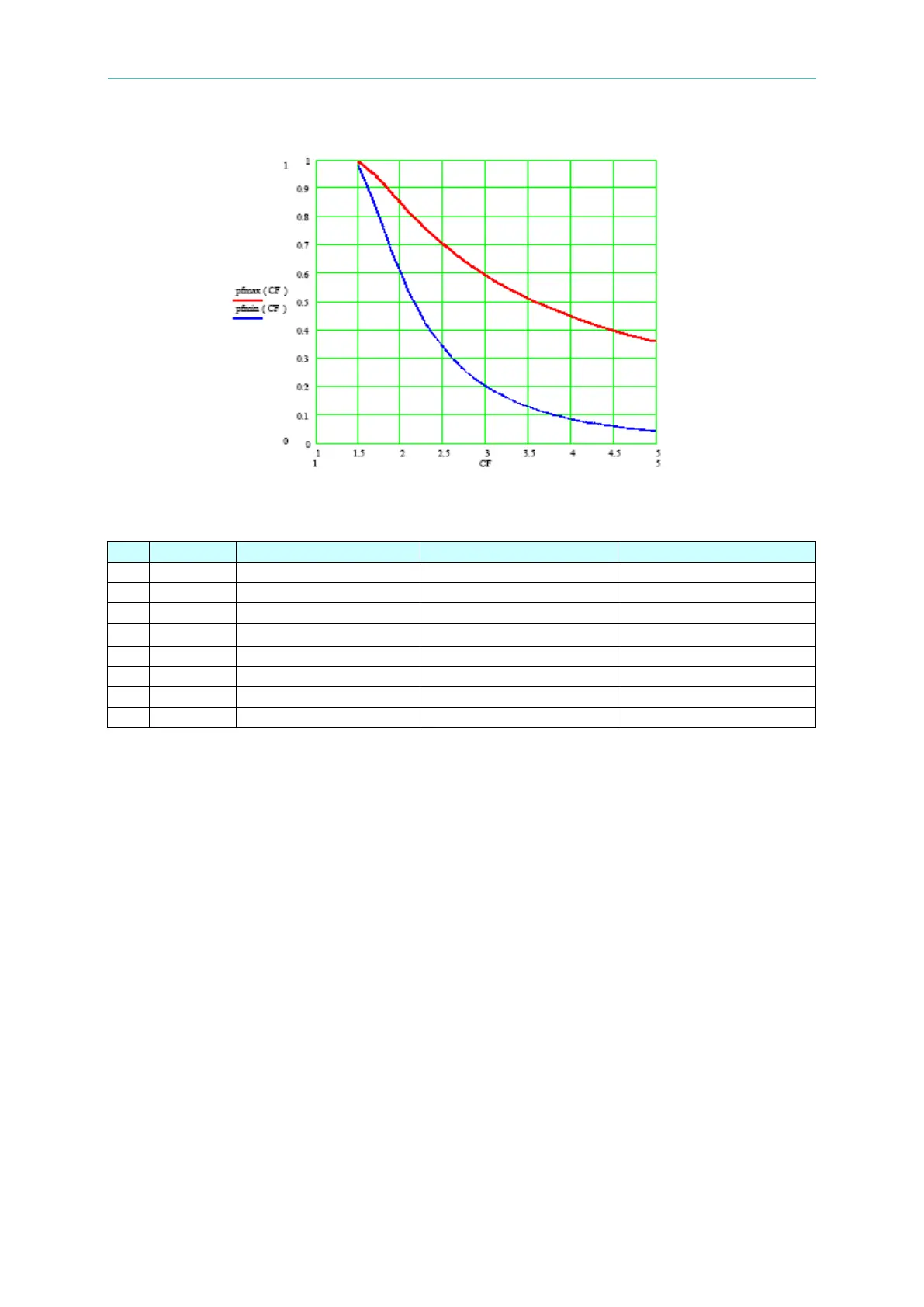
Figure 3-6 The Relationship of PF and CF
Table 3-1 Maximum and Minimum Values of PF in Different CF
If users choose BOTH mode(please refer section 3.6.1) in CC mode(please refer section 3.6)
and CP mode(please refer section 3.8) under AC load simulation(please refer section 3.5),
thus it is needed to input CF and PF values simultaneously.
It is necessary to set CF and PF priority again in BOTH mode. If users’ settings are outside
of the range as in Figure 3-6 and Table 3-1, 63800 Electronic Load will modify users’ settings
to a reasonable range automatically.
Example 1: (when the priority is CF and the output voltage of UUT is
200V
rms
)
a. If users set CF=1.5 and PF=1, however the allowable PF value with CF=1.5 is from 0.977
to 0.993. The system will use a loading with a PF value close to the allowable PF value, in
this case a PF value of 0.993 will be used.
b. If users set CF=1.5 and PF=0.8, however the allowable PF value reasonable range under
CF=1.5 is from 0.977 to 0.993. The system will use a loading with a PF value close to
the allowable PF value, in this case a PF value of 0.977 will be used.
c. If users set CF=3 and PF=0.1, however the allowable PF value reasonable range under
CF=3 is from 0.219 to 0.593. The system will use a loading with a PF value close to the
allowable PF value, in this case a PF value of 0.219 will be used.
 Loading...