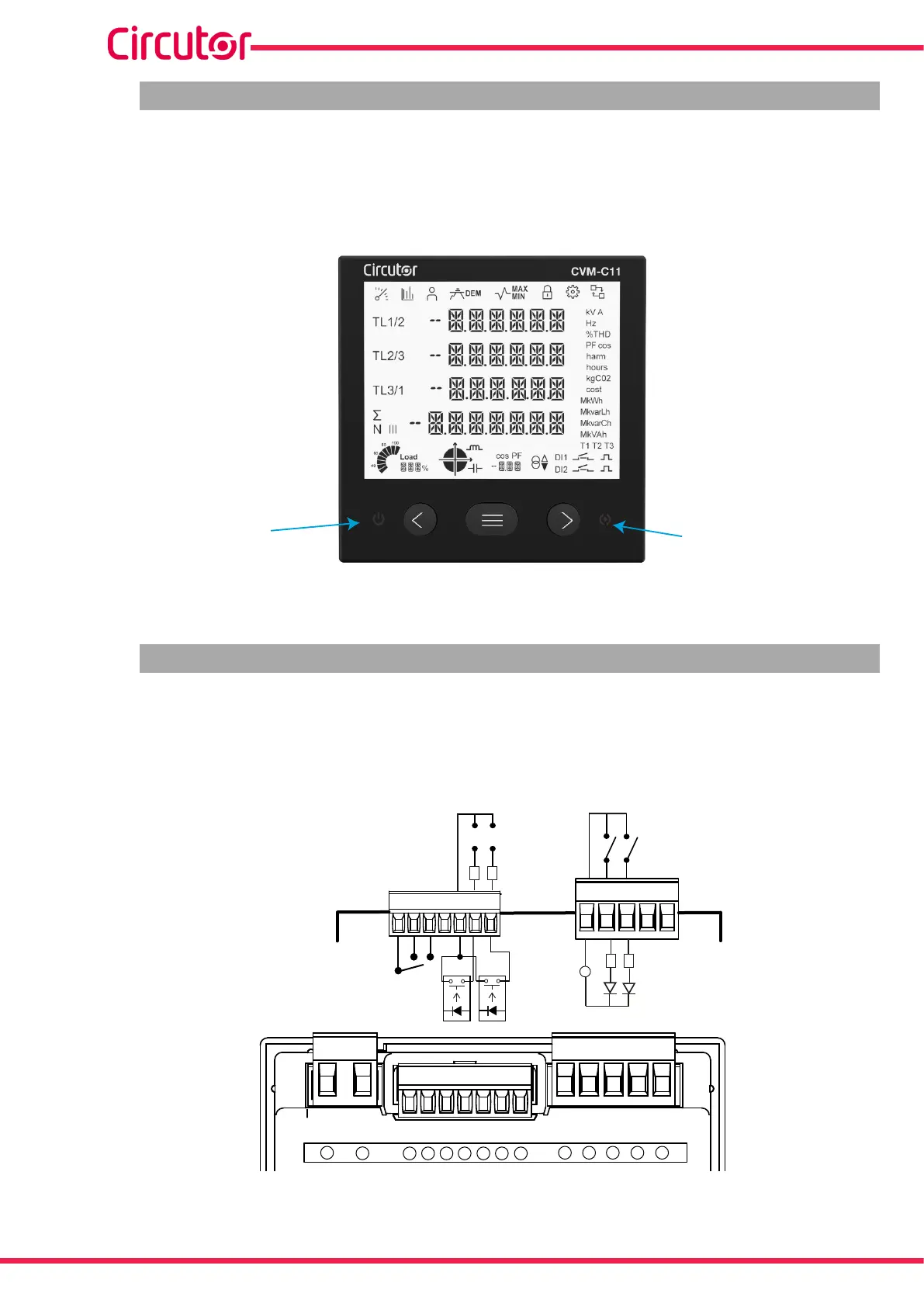
4.4.- LED INDICATORS
The CVM-C11 device has 2 LEDs:
- ON, white color, indicates that the device is on, flashing each second.
- ALARM, red color, indicates that an alarm has been activated if it is on.
LED ON
LED Alarm
Figure 34: LED Indicators of the CVM-C11.
4.5.- RELAYS
El CVM-C11 has 2 alarm relays (terminals 3, 4 and 5 on Figure 1) fully programmable, see “6.25.- PRO
GRAMMING THE ALARM RELAY 1” and “6.26.- PROGRAMMING THE ALARM RELAY 2” (Figure 35).
POWER SUPPLY OUTPUTS INPUTS RS-485
A1(+)
A2(-)
R0C R01 R02
D0C
D01 D02 DIC DI1 DI2
A(+) B(-)
U
L1
U
L2
U
L3
N
IL1
IL2
IL3
IN
S1
S2
S1 S1
S1
S2 S2 S2
P2
P1
P2
P1
P2P1 P2P1
Relé 1 y 2
Relay 1 and 2
R0C
R01 R02
Carga
Load
Fuente externa
External load
Salidas digitales
Digital outputs
D0C
D01 D02
Entradas digitales
Digital inputs
-
DIC
DI1
DI2
4kΩ
4kΩ
Figure 35:Relays, Digital outputs and Digital inputs.
46
CVM-C11
Instruction Manual