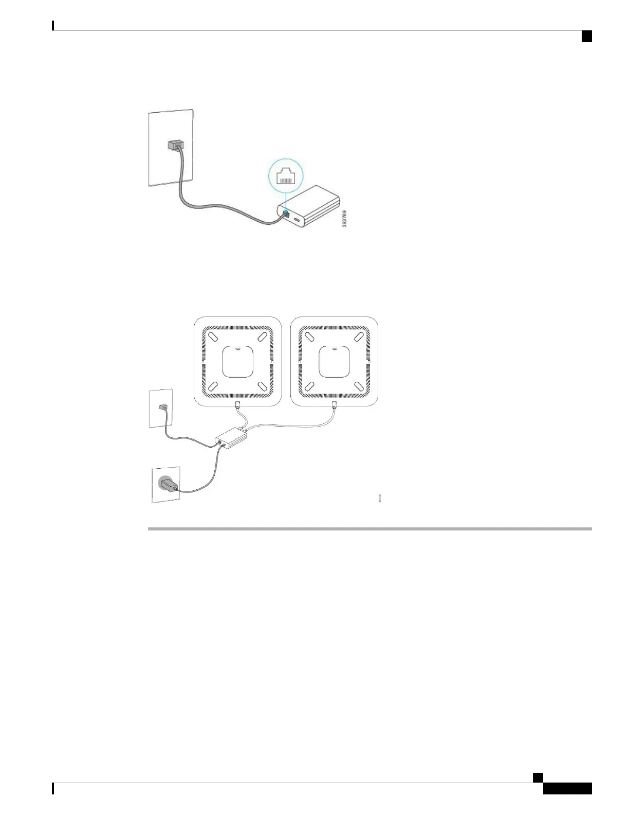
Figure 14: Smart Adapter LAN Port Connected to the LAN Port on the Wall Outlet
Step 4 Connect the first phone to the Smart Adapter using the longer, thicker USB-C cable.
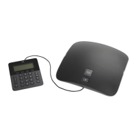
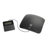
Step 5 Connect the second phone to the Smart Adapter using a USB-C cable.
The following figure shows installation of the conference phone in daisy chain mode.
Figure 15: Conference Phone Installation in Daisy Chain Mode
Related Topics
Daisy Chain Mode, on page 27
One Phone in Daisy Chain Mode Doesn't Work, on page 168
Reboot Your Conference Phone from the Backup Image
Your Cisco IP Conference Phone 8832 has a second, backup image that allows you to recover the phone when
the default image has been compromised.
To reboot your phone from the backup image, perform the following procedure.
Cisco IP Conference Phone 8832 Administration Guide for Cisco Unified Communications Manager
35
Cisco IP Conference Phone Installation
Reboot Your Conference Phone from the Backup Image
 Loading...