9-17
Cisco SCE8000 GBE Installation and Configuration Guide
OL-19897-02
Chapter 9 Removal and Replacement Procedures
Removing and Replacing Modules
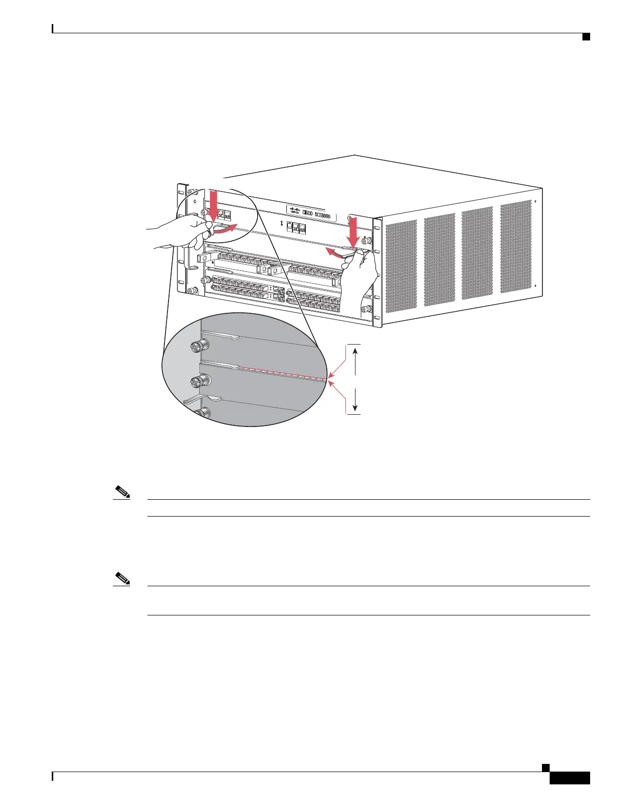
Step 8 Carefully slide the module into the slot until the EMI gasket along the top edge of the module makes
contact with the module in the slot above it and both ejector levers have closed to approximately 45
degrees with respect to the module faceplate. (See Figure 9-12.)
Figure 9-12 Clearing the EMI Gasket
Step 9
Using the thumb and forefinger of each hand, grasp the two ejector levers and press down to create a
small (0.040 inch [1 mm]) gap between the module EMI gasket and the module above it. (See
Figure 9-12.)
Note Do not press down too forcefully on the ejector levers. They will bend and be damaged.
Step 10 While pressing down, simultaneously close the left and right ejector levers to fully seat the module in
the backplane connector. The ejector levers are fully closed when they are flush with the module
faceplate. (See Figure 9-13)
Note Failure to fully seat the module in the backplane connector can result in incorrect operation and/or error
messages.
274457
F
AN ST
ATU
S
SC
M
1
SC
M
2
S
I
P
3
4
S
C
E
800
0-FAN
SCE80
0
0
SP
A
I
N
T
ERFA
CE
PROCESSO
R
0
2
S
T
A
T
US
SYS
T
E
M
POW
ER
OP
T
I
C
A
L
BYPASS
STA
T
U
S
A
U
X
P
ORT 2
M
A
ST
E
R
SC
E
8
0
00
EXT
EN
D
E
D
SERVICE
C
O
N
TROL
MOD
U
L
E
OPTIC
A
L
B
YP
A
S
S
O
P
T
IC
AL
B
YP
A
SS
CON
S
O
L
E
P
O
R
T1
SCE
8
0
0
0
-S
C
M-
E
S
CE8
0
0
0
-SI
P
ST
AT
U
S
S
P
A
-
1
X
1
0
G
E
-
L
-V
2
1
3
1
0
/
1
00
/
1
00
0
LIN
K
/
A
C
TIVE
1
0
/10
0
/
1000
LI
N
K
/
A
CT
IVE
0
2
CTRL
A
1
R
x
Tx
B1 C
1D
1
A2
B
2
C
2
D
2
L2
L1
A
B
C
D
A
C
B
D
OPB-
S
CE
8K-
2L-
M
M
CTRL
A
1
R
x
Tx
B1 C
1
D
1
A2
B2
C
2
D
2
L2
L1
A
B
C
D
A
C
B
D
OPB-
S
CE
8K-
2L-MM
1
3
OP88K-
H
D
-
E
XT-
P
NL
C
TR
L
A1
R
x
T
x
B1
C
1D
1A2
B2
C
2
D
2
L2
L1
A
B
C
D
A
C
B
D
OP
B-
S
CE8K-2
L-
MM
C
TR
L
A1
R
x
T
x
B
1
C
1D
1
A2
B2
C
2
D
2
L2
L1
A
B
C
D
A
C
B
D
OP
B-
S
CE
8K-
2
L-
MM
SPA-8X1GE-V2
3
4
STA
T
U
S
2
1
0
A/L
5
6
7
A/L
A/L
A/L
A/L
A
/L
A/L
A
/L
S
T
AT
U
S
S
P
A
-
1
X1
0
G
E
-
L
-
V
2
SPA-8X1GE-V2
3
4
S
T
A
T
U
S
2
1
0
A
/L
5
6
7
A/L
A
/L
A
/L
A
/L
A/L
A
/L
A
/L
1mm
Gap between the module
EMI gasket and the
module above it.
Press down
Press down