NGT—Technical description (2010)
72 NGT Transceiver System Technical Service Manual
Supply voltages
Handset
The supply voltages for the handset are shown in Table 18.
Junction box
The supply voltages for the junction box are shown in Table 19 and Table 20.
Drawing 04-03125
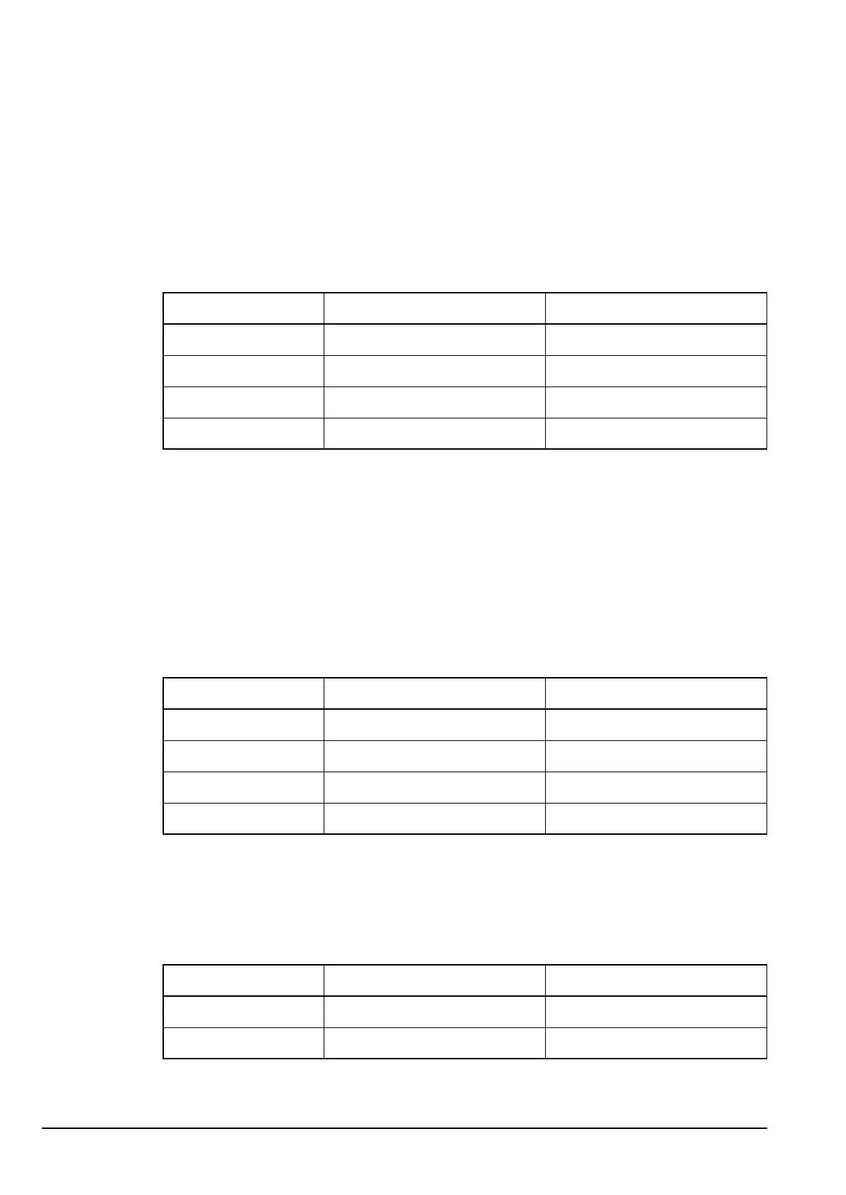
Table 18: Supply voltages for the Handset PCB in the handset
Supply Description Source
Standby +5.4 V when transceiver is off ext from junction box
Handset power +9.2 V when transceiver is on ext from junction box
+5 V +5 V regulated supply IC10
–9 V –9 V for IC7 IC5
ALTERNATIVE TEXT
Drawing 04-03201, or
Drawing 04-03423
Table 19: Supply voltages for the Audio PCB in the junction box (04-03201 or
04-03423)
Supply Description Source
A (protected) Unregulated battery supply ext from RF unit
+10 V +10 V regulated supply IC12
+5 V +5 V regulated supply IC13
+5 VQ +5 V quiet for opamp bias IC13 (filtered)
Drawing 04-03133
Table 20: Supply voltages for the Microprocessor PCB in the junction box
Supply Description Source
+5 V +5 V digital supply IC13
A (protected) Unregulated battery supply from RF unit