NRI—Fault finding
NGT Transceiver System Technical Service Manual 273
LED indicators
Most devices in a remote control NGT system have a LED indicator on their front panel.
The different colours of the LED indicators and timing of flashes indicates the state of
the device. The LED indicators are useful in detecting fault conditions of the units in
your remote control NGT system.
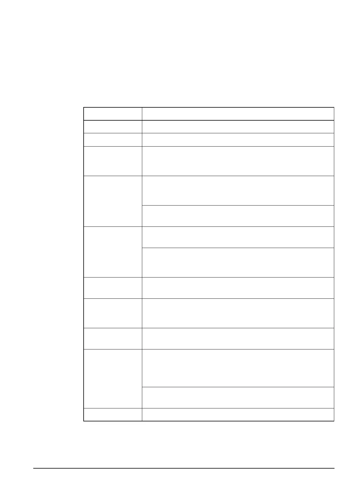
Table 7: Description of LEDs
State of LED Description
Off The power to the system is off.
Constant green The device is operating normally.
Fast flashing green Firmware has been downloaded successfully to the device and the
transceiver must be switched off then on again for the system to
recognize the new firmware.
Slow flashing
green
The device has successfully powered up but has not had any
communication with another CIB device. This usually indicates a
faulty CIB cable connection.
During normal operation, the system is momentarily under a very
high processing load.
Constant yellow The device is in its powered up state, i.e. the device is on but not in
use.
The device is in the process of undergoing power up tests and start
up procedures, i.e. most devices are in this state for a few seconds
after the system is switched on.
Fast flashing
yellow
The device is waiting for firmware to be downloaded.
Slow flashing
yellow
The device is in test mode or running tests. In this state, the device
cannot respond or is very slow to respond to service requests from
the rest of the system.
Constant red The device has a fatal error condition and the system ceases to
operate.
Fast flashing red The device has a temporary error condition. This is usually caused
by an external fault condition, e.g. when an RF unit detects that the
battery voltage has decreased to a low level. The LED remains in
this state while the condition exists.
During a firmware download, verification of the image is in
progress.
Slow flashing red The device is unused.