8571—Overview and specifications
324 NGT Transceiver System Technical Service Manual
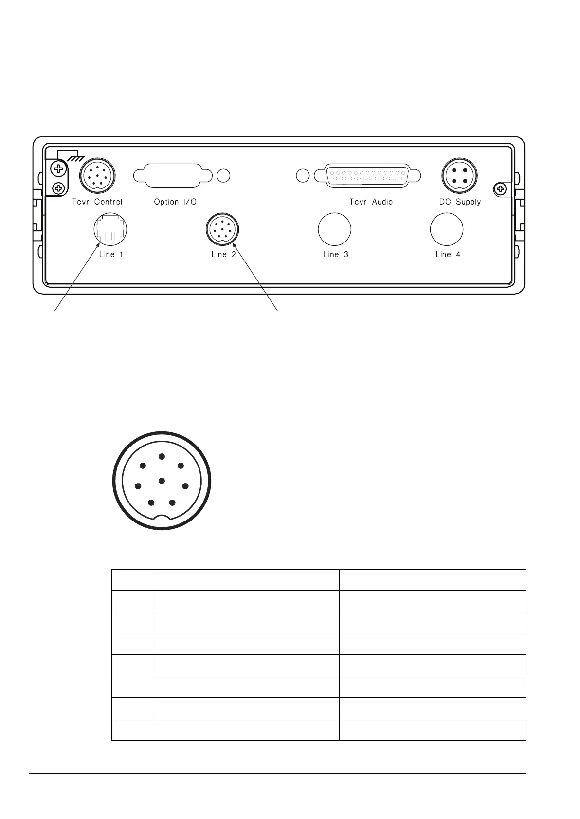
Pin connections
Figure 2: Rear panel of the 8571
Pinouts of the Tcvr Control connector on the 8571
Figure 3: Front view of the Tcvr Control connector on the 8571
Table 1: Pinouts of the Tcvr Control connector on the 8571
Pin no. Function Signal level
1 Rx audio 1 V p–p
2–3 Ground 0 V
4RxD ±10 V logic approx.
5RTS ±10 V logic approx.
6TxD ±10 V logic approx.
7CTS ±10 V logic approx.
8 Rx audio ground 0 V
2-wire connector 4-wire connector
1
2
3
4
5
6
7
8