NGT Transceiver System Technical Service Manual 363
8571—Drawings
The drawings in this section consist of the mechanical and electrical diagrams required
to maintain the 8571.
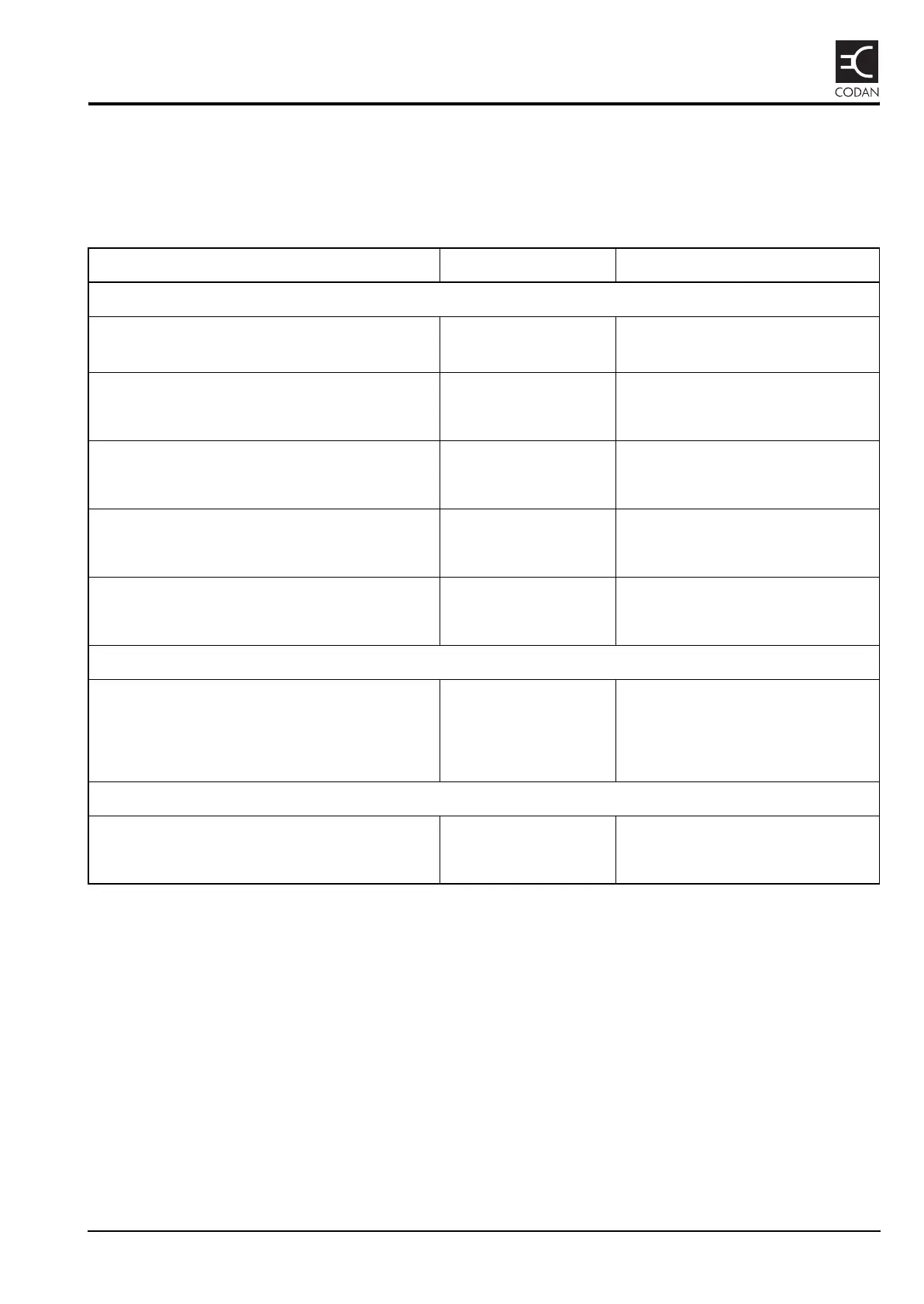
Table 11: 8571—list of drawings
Title Drawing Drawing number
NGT Split-site Remote Interface 8571
8571 Remote Control (NGT) Interface
Assembly
08-05994 (sheet 1)
08-05994 (sheet 2)
Dual Line Equaliser Circuit diagram 04-02541
PCB assembly 08-03905
Microprocessor & Tcvr Interface Circuit diagram 04-02690
PCB assembly 08-03993
Backplane Circuit diagram 04-02691
PCB assembly 08-05995
General Purpose Input/Output Circuit diagram 04-02852
PCB assembly 08-04644
Line Interface
Line Isolating Interface Circuit diagram 04-02487
Line Isolating Unit PCB assembly 08-03817
4-wire Interface PCB assembly 08-03995
Options
Option 2W 8571 Fitting instructions 15-10509-001
Option 4W 8571 Fitting instructions 15-10510-001