NGT—Checks and adjustments
NGT Transceiver System Technical Service Manual 171
Adjusting carrier re-insertion
To adjust carrier re-insertion:
1 Select test channel 16 with AM mode.
1 Unplug the coaxial cable between the PA PCB and the RF/IF PCB in the RF unit.
1 Connect an oscilloscope with a 50 Ω termination to the Tx test point on the
RF/IF PCB.
1 Using the transceiver test unit, apply an audio signal of 1 kHz at a level of
300 mV p–p to:
• the audio input on the 15-way GPIO connector on the junction box or 2012 RF
Unit (see Figure 40 on page 170), or
• the 2011 RF Unit via the NGT test handset (see Figure 41 on page 170)
1 Hold down PTT.
1 Adjust R217 (near the SSB filter Z201) for 100% modulation.
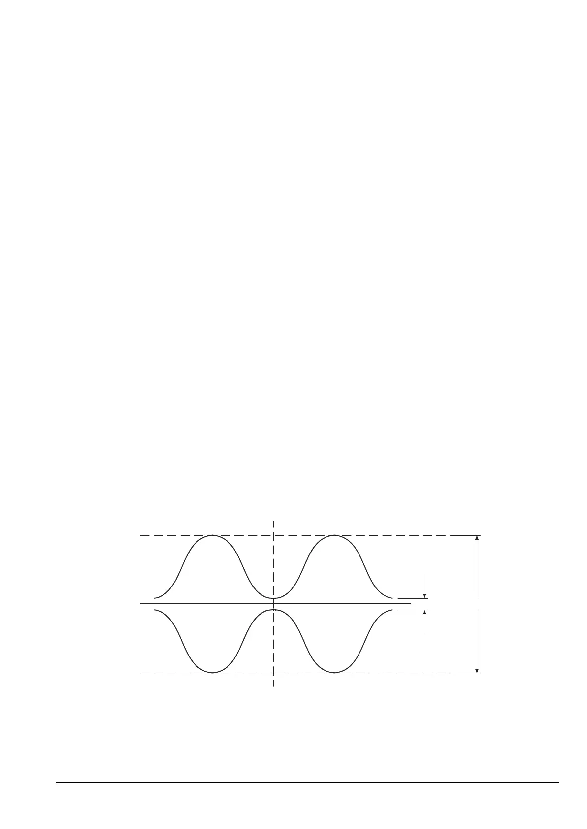
1 Rotate R217 clockwise to set it to approximately 90% modulation (see Figure 42).
Figure 42: Graph showing adjustment to 90% modulation
1 Release PTT.
ALTERNATIVE TEXT
Drawing 08-05261 (sheet 2) or 08-05889 (sheet 2)
NOTE If the PCB issue status is -06 or earlier, see drawing 08-05889 (sheet 2).
NOTE
The exciter output level must be set before this adjustment is made (see
page 170, Adjusting the exciter output level).
NOTE
The transceiver must be in Service mode to perform this check (see
page 154, Accessing Service mode).
¼ Div
6 Div