NGT—Checks and adjustments
NGT Transceiver System Technical Service Manual 187
Checking intermodulation
The test channels 9 to 30 can be used to check for IMD. To facilitate checking each band,
there is a test channel allocated near the bottom, top and centre of each band.
To check the IMD:
1 Connect a 50 Ω dummy load to the RF connector ( ).
1 Connect a spectrum analyser via a 47 kΩ resistor to the RF connector (see
Figure 44).
This provides a low-level output for the spectrum analyser.
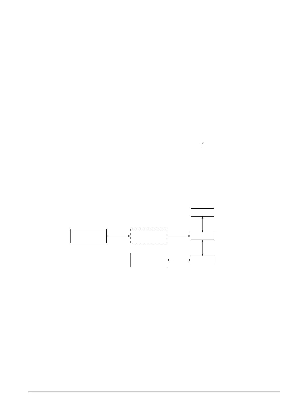
Figure 44: Setup for checking intermodulation distortion
1 Connect a signal generator to provide two-tone audio (700 Hz and 2300 Hz) via the
test unit to:
• the audio input on the 15-way GPIO connector on the junction box or 2012 RF
Unit (see Figure 40 on page 170), or
• the 2011 RF Unit via the NGT test handset (see Figure 41 on page 170)
ALTERNATIVE TEXT
Drawing 08-05416 or 08-05910 (sheet 1)
NOTE If the PCB issue status is -04 or earlier, see drawing 08-05910 (sheet 1).
NOTE
The bias gain or active bias must be set before any intermodulation tests
are performed (see page 182, Adjusting the bias gain or page 184,
Adjusting the active bias).
NOTE
The transceiver must be in Service mode to perform this check (see
page 154, Accessing Service mode).
Signal
generator
Spectrum
analyser
50 W load
Transceiver
47 kW
Test
equipment