NGT—Technical description (2010)
78 NGT Transceiver System Technical Service Manual
RF unit—Application Processor PCB transmit path
The transmit audio goes to IC5 pin 28. This audio interface device contains an ADC and
a DAC.
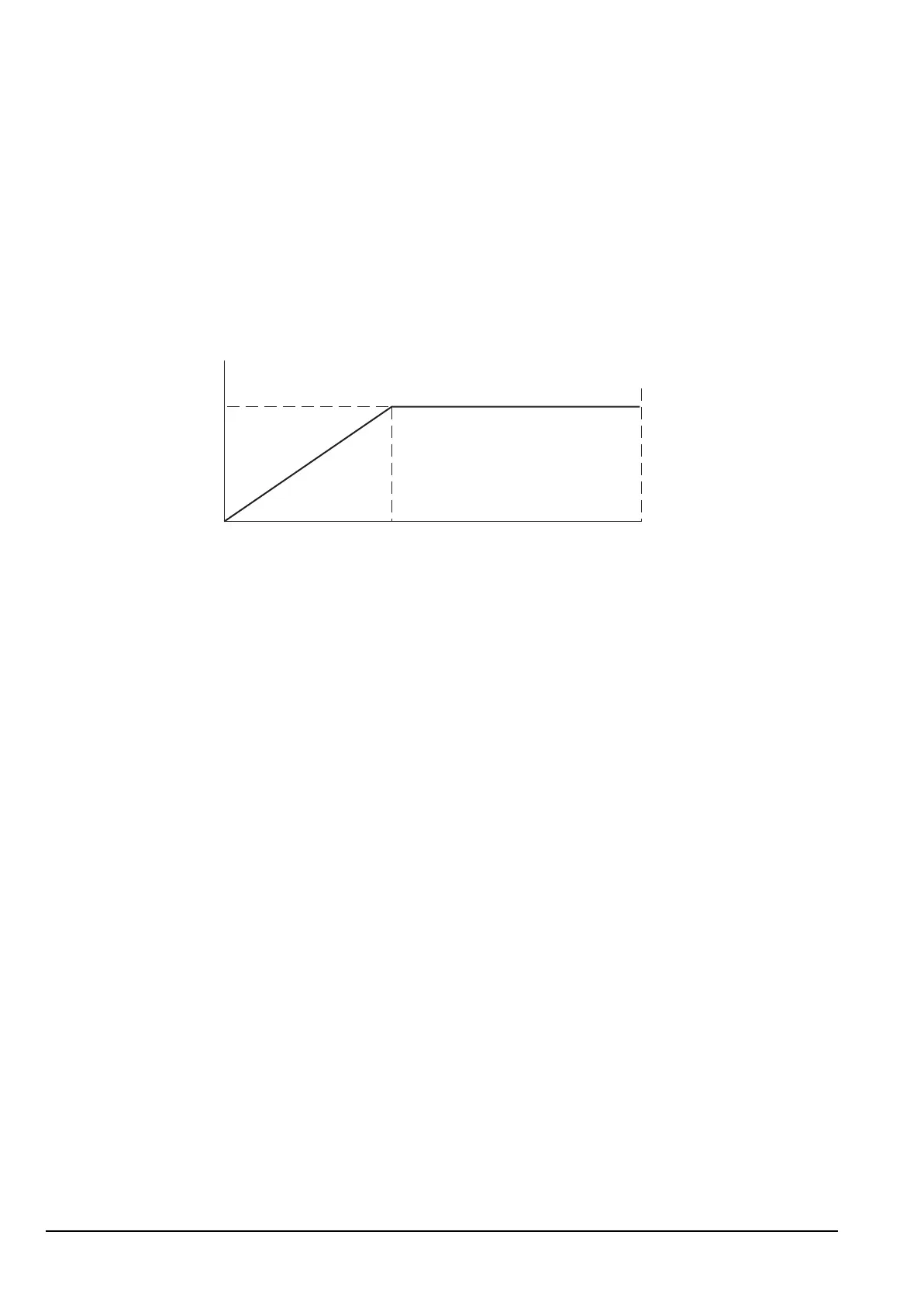
The analog transmit audio is sampled and converted by IC5 into digital format. A
compression function is applied to the digital audio as shown in Figure 20 below.
Figure 20: Representation of compression function by IC5
The decay time constant is controlled by firmware and can be varied depending on the
type of transmission. For example, for speech, the time constant needs to be short, but for
data it needs to be lengthened to improve the BER.
The DAC outputs of IC5 pins 3 and 4 are summed together in IC7/A to produce an
output of 1 V p–p. This output then goes via the Audio Interface PCB to the RF/IF PCB.
The output level, which is controlled by firmware, is halved when AM is transmitted or
low power is selected.
Drawing 04-03108 (sheet 1)
Input Level
Output Level
1 V
200 mV 2 V