System Board
Description Spare part number
System board (includes processor and replacement thermal material) 616662-001
The system board is secured with four screws. The system board includes a processor, which is
soldered onto the board.
1. Prepare the computer for disassembly (
Preparation for Disassembly on page 77).
2. Remove the access panel (
Access Panel on page 78).
3. If applicable, remove the expansion board (
Expansion Cards on page 92).
4. Disconnect all cables connected to the system board, noting their location for reinstallation.
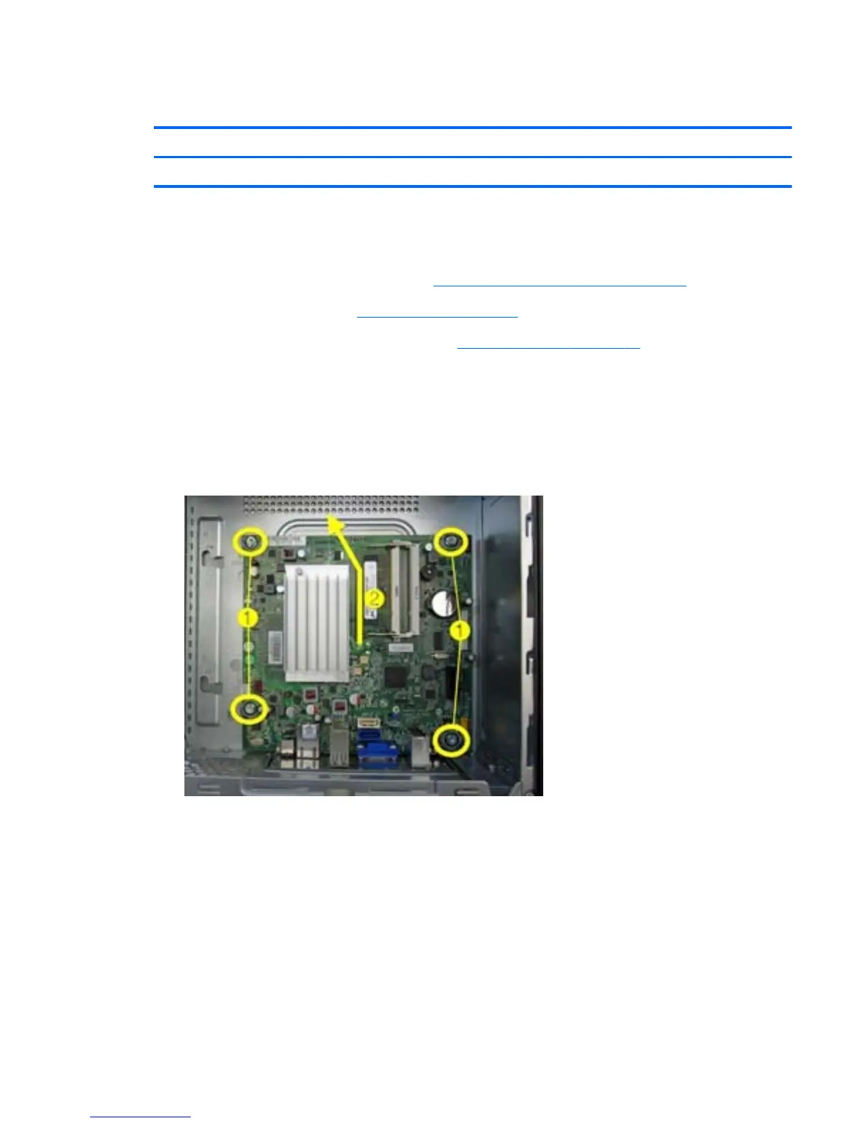
5. Remove the remaining four screws (1) that secure the system board to the chassis.
6. Slide the system board toward the front of the computer (2) to disengage the I/O panel from the
rear of the chassis, and then lift the system board out of the computer.
Figure 7-30 Removing the system board
When reinstalling the system board, first insert the I/O panel back into the slots in the rear of the
chassis, and then align the board with the chassis screw holes. angle the connectors into place under
the I/O panel spring fingers to avoid bending them down and blocking openings.
Use the diagonal rule when replacing system board screws.
System Board
103
 Loading...