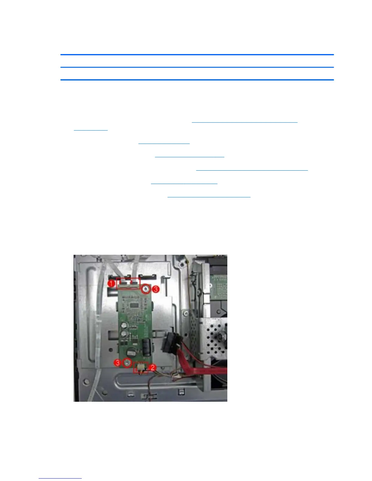
Driver Board
Description Spare part number
Driver board PHB (for panel) 623388-001
The driver board is mounted atop the optical drive cage. The board connects three display cables and
is secured with two screws.
1. Prepare the computer for disassembly (see
Preparing to disassemble the computer
on page 106).
2. Remove the stand (see
Stand on page 111).
3. Remove the hinge cover (see
Hinge Cover on page 112).
4. Remove the memory/optical drive cover (see
Memory/Optical Drive Cover on page 107).
5. Remove the rear cover (see
Rear Cover on page 113).
6. Remove the rear metal cover (see
Rear Metal Cover on page 118).
7. Disconnect the two LIF connectors on the top of the board (1) and the connector on the bottom
of the board (2).
8. Remove the two silver Torx 2.5x7.0 screws that secure the board to the computer (3), and then
lift the board up and out of the computer..
Figure 8-16 Removing the driver board
To replace the driver board, reverse the removal procedures.
122 Chapter 8 Removal and Replacement Procedures All-in One (AIO) Chassis
 Loading...