Power Switch/LED Assembly
Description Spare part number
Power switch/LED assembly 622204-001
The power switch/LED assembly is secured with a tab and hooks. The cable is held in place with
chassis clips located under the optical drive.
1. Prepare the computer for disassembly (
Preparation for Disassembly on page 43).
2. Remove the access panel (
Access Panel on page 44).
3. Lay the computer on its side with the front facing toward you.
4. Remove the front bezel (
Front Bezel on page 45).
5. Remove the optical drive (
Removing an Optical Drive on page 59).
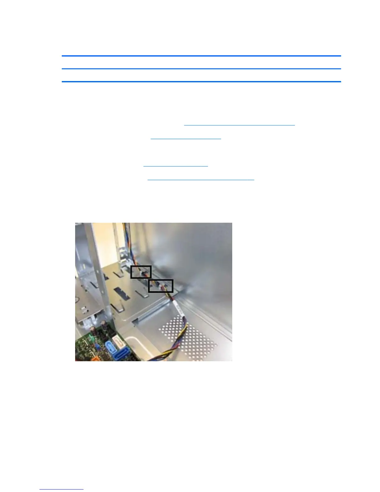
6. Disconnect the braided cables from the black system board connector labeled J18.
7. Remove the power switch cable from the clips located in the optical drive bay on the inside of
the chassis.
64 Chapter 6 Removal and Replacement Procedures Microtower (MT) Chassis
 Loading...