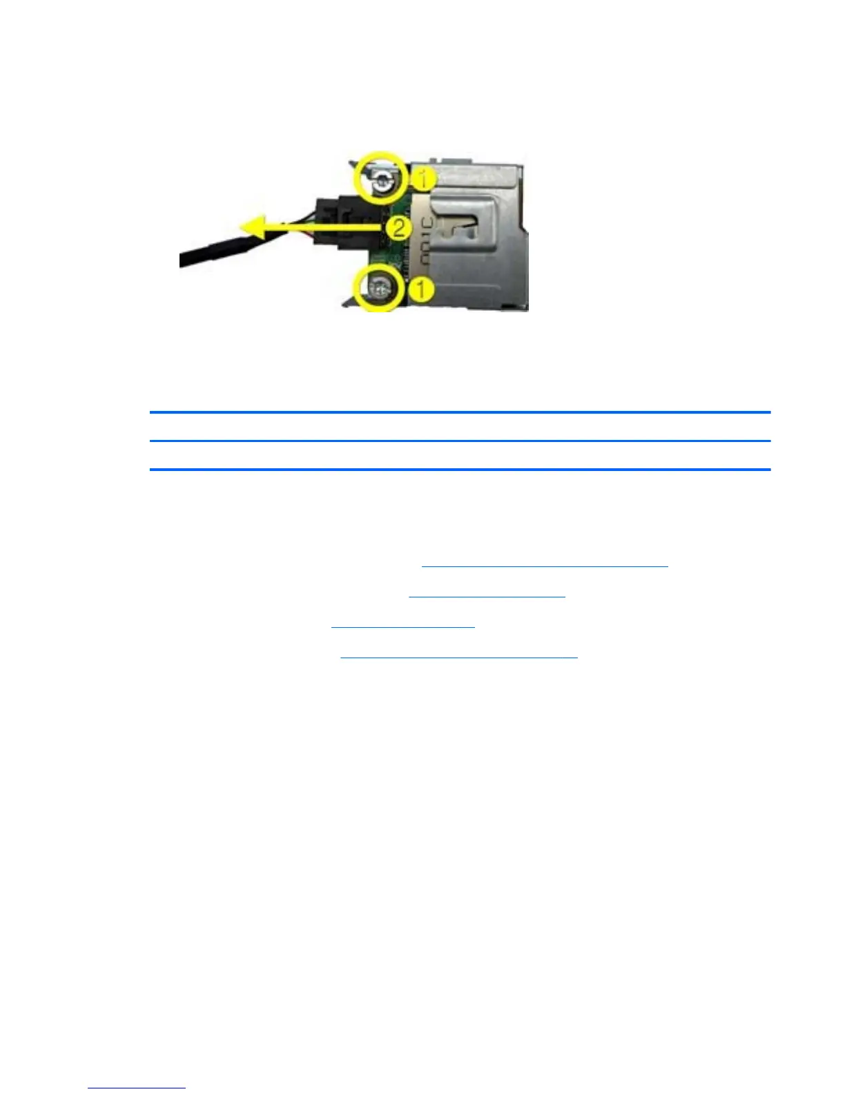
8. If you need to remove the card reader board from the bracket, remove the two Torx screws (1)
that secure the board to the bracket, and then slide the board out of the bracket (2).
Figure 7-25 Removing the Card Reader Board from the Bracket
To reinstall the card reader, reverse the removal procedure.
Power Switch/LED Assembly
Description Spare part number
Power switch/LED assembly 628801-001
The power switch/LED assembly is located on the top, right of the computer. The assembly is held in
place with tabs and hooks.
1. Prepare the computer for disassembly (
Preparation for Disassembly on page 77).
2. Remove the computer access panel (
Access Panel on page 78).
3. Remove the front bezel (
Front Bezel on page 79).
4. Remove the optical drive (
Removing an Optical Drive on page 87).
5. Disconnect the cable from the black system board connector labeled P22.
6. Remove the cable from the metal clamps on the side of the drive cage. This step may require a
flat blade screwdriver to lift the clamps enough to remove the cable.
Power Switch/LED Assembly
99
 Loading...