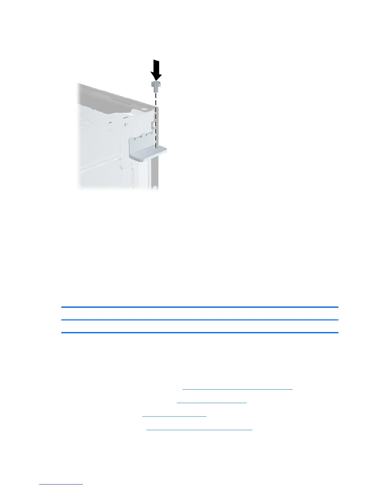
11. Replace the screw that secures the slot cover retainer in place.
Figure 7-21 Replacing the Slot Cover Retainer Screw
12. Connect external cables to the installed card, if needed. Connect internal cables to the system
board, if needed.
13. Replace the optical drive.
14. Replace the front bezel and access panel.
15. Reconnect the power cord and any external devices, then turn on the computer.
16. Reconfigure the computer, if necessary. Refer to the F10 Setup Utility chapter for instructions on
using Computer Setup.
Front USB Panel
Description Spare part number
Front USB panel 622194-001
The front panel includes two USB connectors and two audio connectors. The panel is housed in a
bracket, and the assembly secured to the front of the computer with one screw.
The board can be removed from the bracket by removing two screws.
1. Prepare the computer for disassembly (
Preparation for Disassembly on page 77).
2. Remove the computer access panel (
Access Panel on page 78).
3. Remove the front bezel (
Front Bezel on page 79).
4. Remove the optical drive (
Removing an Optical Drive on page 87).
96 Chapter 7 Removal and Replacement Procedures Small Form Factor (SFF) Chassis
 Loading...