26 - Hardware Installation DeviceMaster Installation and Configuration Guide: 2000594 Rev. F
Hardware Installation
3. Apply power to the DeviceMaster RTS by connecting the AC power adapter to the DeviceMaster, the
power cord to the power adapter, and plugging the power cord into a power source. See
External Power
Supply Specifications on Page 139 if you want to provide your own power supply.
4. Verify that the PWR LED has completed the boot cycle and network connection for the DeviceMaster RTS
is functioning properly using the table below.
5. Go to Initial Configuration on Page 33 to configure the DeviceMaster for use.
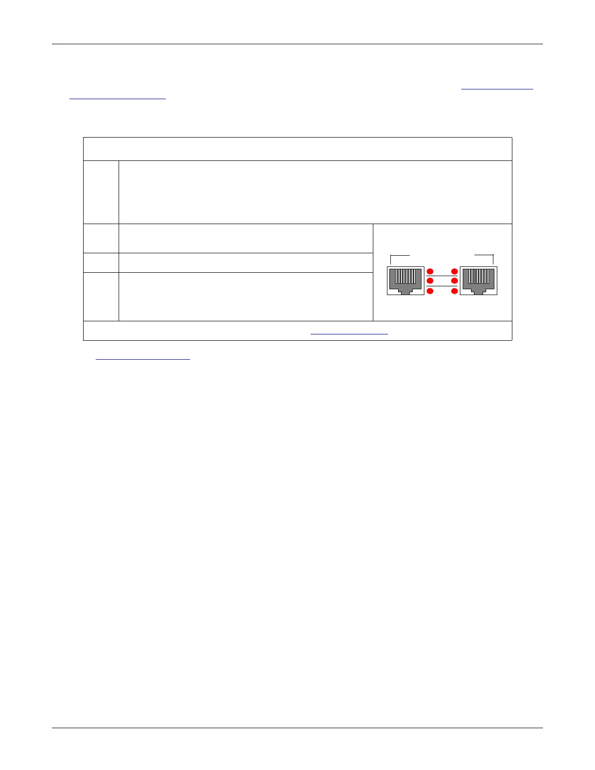
DeviceMaster RTS 16-Port (External Power Supply) LED Descriptions
Red
LED
Red LED on the front panel of the DeviceMaster is lit, indicating you have power and
it has completed the boot cycle.
Note: The LED flashes while booting and it takes approximately 15 seconds for the
Bootloader to complete the cycle. When the Bootloader completes the cycle, the
LED has a solid, steady light that blinks approximately every 10 seconds.
LNK
ACT
The red LNK ACT LED is lit, indicating that you have
a working Ethernet connection.
COL If the red COL LED is lit, there is a network collision.
100
If the red 100 LED is lit, it indicates a working 100
MB Ethernet connection (100 MB network, only). If
the LED is not lit, it indicates a 10 MB Ethernet
connection.
Note: For additional LED information, go to the Status LED table on Page 148.
LNK
ACT
COL
100
10/100 NETWORK
UP DOWN