Secon 10 - Diagnosc and Maintenance Procedures
Technical Manual
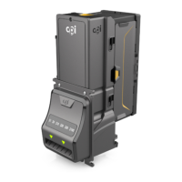
13. Take the new lter head assembly from the service kit.
Holding the new lter assembly as shown, turn the
locking ring an-clockwise to its open posion,
indicated by the two arrows.
Place the lter unit up into the lter holder and turn the
green locking ring clockwise to lock it into place
14. Re-assemble the wiper arm (d) to the lter holder
assembly.
Ensure that the wiper arm is located under the coee
outlet pipes as shown (e).
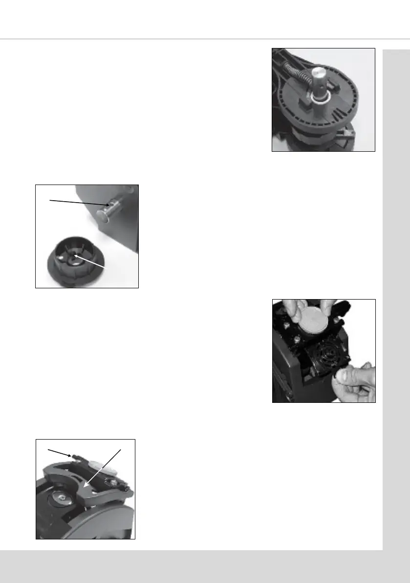
11. Ensure the plasc washer (a) if ed is placed correctly
over the input sha (long side) as shown.
Re-assemble the front and rear brewer panels to the
central piston chamber/swing arms assembly using the
three retaining screws/locknuts. Check and ensure that
the brewer release lever mechanism operates
correctly.
c
b
12. Re-t the brewer drive coupling to the input sha
ensuring that the raised ‘pip’ (b) lines up with its locang
dimple (c) on the input sha.
Ensure that the capve lock nut is retained in the plasc
drive coupling moulding. Ret the bolt to secure the
brewer drive coupling to the input sha.
e
d