Chapter 2
Panels & LED Indicators
2.1.6 Earth Grounding
An earth ground hole (next to AC or DC power supply) is provided on the left side of the front panel with an earth ground
sign next to it. Grounding the device can help to release leakage of electricity to the earth safely so as to reduce injuries
from electromagnetic interference (EMI).
Prior to connecting to the power, it is important to connect the ground wire to the earth. Follow steps below to install
ground wire:
Step 1. Prepare one suitable ground screw and one grounding cable.
Step 2. Attach the grounding screw to the ring terminal of the grounding cable. Make sure that the grounding cable is
long enough to reach the earth.
Step 3. Use a screwdriver (or other tools) to fasten the grounding screw on the earth ground hole securely.
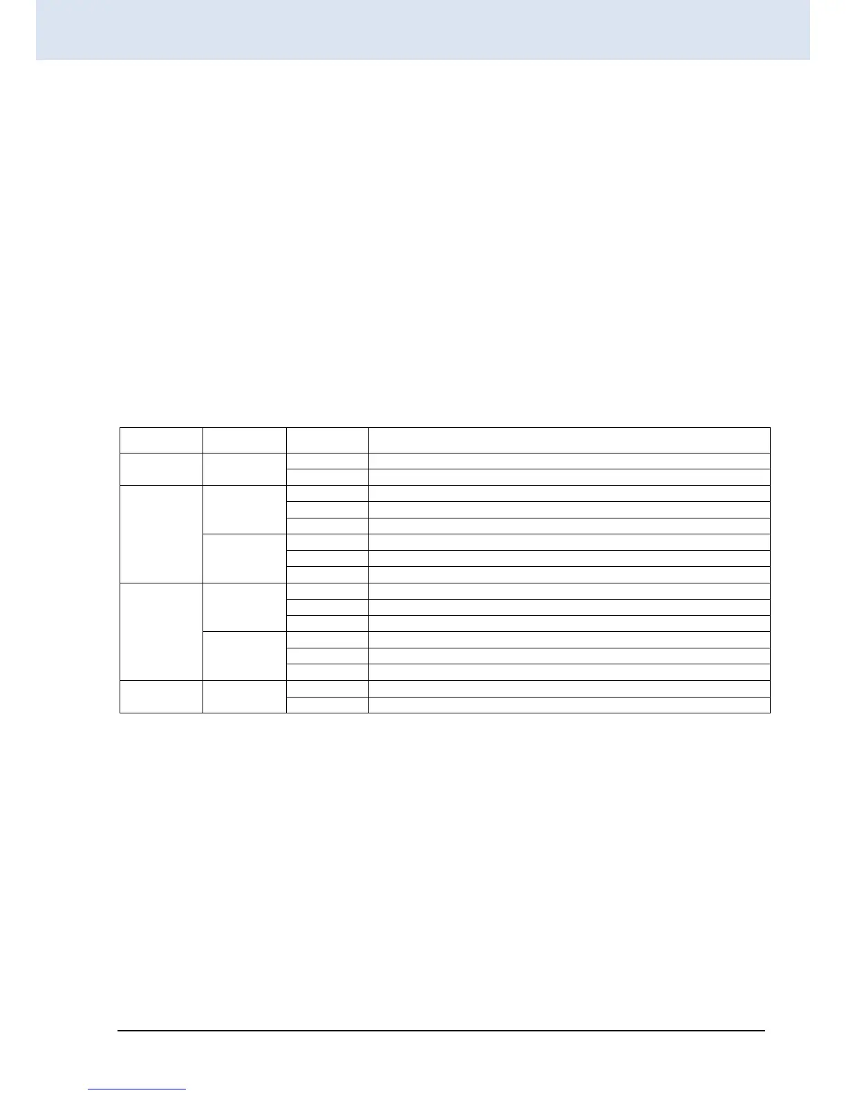
2.2 LED Indicators
LED indicators are located on the front panel of the unit. Each port has a corresponding LED indicator that provides a
visual and real-time indication of the current operating state. A description of these LED indicators is provided below.
The switch is receiving power.
The switch does not receive power or is in standby mode.
The fiber port link is up and operating at 1000Mbps.
The fiber port is receiving and transmitting traffic.
The fiber port link is down.
The fiber port link is up and operating at 100Mbps.
The fiber port is receiving and transmitting traffic.
The fiber port link is down.
When the LAN port is up and operating at 1000Mbps.
The LAN port is receiving and transmitting traffic.
The LAN port link is down.
When the LAN port is up and operating at 10/100Mbps.
The LAN port is receiving and transmitting traffic.
The LAN port link is down.
Fiber ports are up and operate normally.
 Loading...