22
Icon Note
1~4
ALARM 1 to ALARM 4. The alarm becomes active in low
voltage.
NO1 C1,NO2 C2,NO3 C3,NO4
C4
Four
groups of normal open activation output (on/off
button)
GND
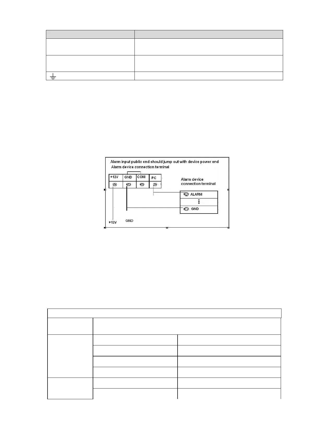
2.4.2 Alarm Input Port
Please refer to the following sheet for more information.
Grounding alarm inputs. Normal open or Normal close type)
Please parallel connect COM end and GND end of the alarm detector (Provide external power to the
alarm detector).
Please parallel connect the Ground of the NVR and the ground of the alarm detector.
Please connect the NC port of the alarm sensor to the NVR alarm input(ALARM)
Use the same ground with that of NVR if you use external power to the alarm device.
Figure 2-18
2.4.3 Alarm Output Port
Provide power to peripheral alarm device.
To avoid overloading, please read the following relay parameters sheet carefully.
RS485 A/B cable is for the A/B cable of the PTZ decoder.
2.4.4 Alarm Relay Specifications
Model:
JRC-27F
Material of the
contact
Silver
Rating value
(Resistance
load)
Contact load
30V DC 1A,125V AC 0.5A
Maximum switch power
62.5VA/30W
Maximum switch voltage
125V AC,60V DC
Maximum switch current
2A
Insulation Between loop and the contact
1000V AC 1 minue
Between breaking contact
400V AC 1 minue

 Loading...