1754
[69.1]
209
[8.2]
1282
[50.5]
386
[15.2]
156
[6.2]
23
[0.9]
25
[1]
161
[6.3]
1931
[76]
170
[4.2]
213
[8.4]
320
[12.6]
1978
[77.9]
1953
[76.9]
107
[4.2]
213
[8.4]
320
[12.6]
1
280
[11]
374
[14.7]
411
[16.2]
420
[16.5]
130
[5.1]
1760
[69.3]
130
[5.1]
668
[26.3]
130BD465.10
2
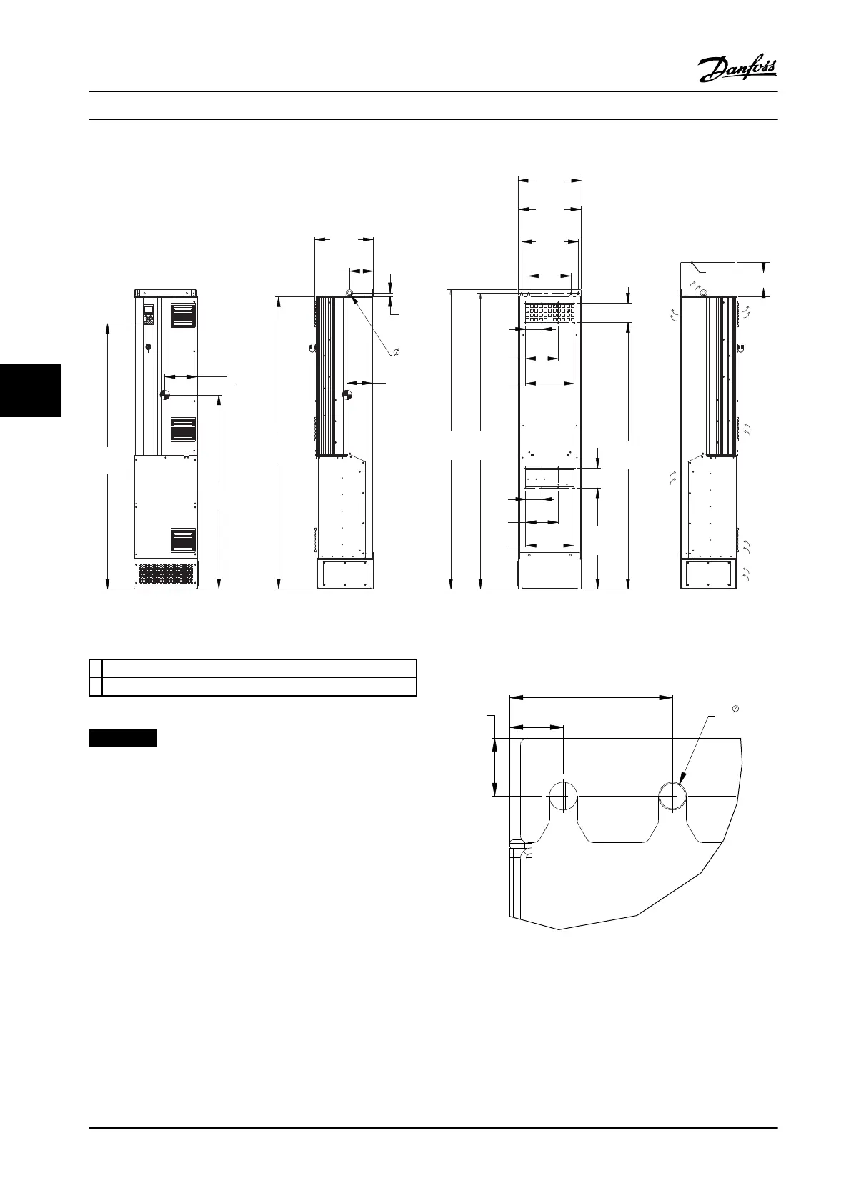
Figure 6.19 Mechanical Dimensions, D7h
1
Ceiling
2 Air space outlet minimum 225 mm [8.9 in]
Table 6.13 Legend to Figure 6.19
NOTICE!
If using a kit to direct the airflow from the heatsink to
the outside vent on the back of the adjustable frequency
drive, the required ceiling clearance is 4 in [100 mm].
70
[2.8]
25
[1.0]
23
[0.9]
11
[0.4]
4X
130BD520.10
Figure 6.20 Top Mounting Hole Dimension Detail, D7h
Mechanical Installation Design Guide
118 Danfoss A/S © Rev. 2014-02-10 All rights reserved. MG34S222
66
 Loading...


