1699
[66.9]
1400
[55.1]
215
[8.5]
2236
[88]
406
[16]
156
[6.2]
23
[0.9]
25
[1]
162
[6.4]
2284
[89.9]
2259
[88.9]
107
[4.2]
213
[8.4]
320
[12.6]
107
[4.2]
213
[8.4]
320
[12.6]
420
[16.5]
411
[16.2]
374
[14.7]
280
[11]
130
[5.1]
130
[5.1]
2065
[81.3]
973
[38.3]
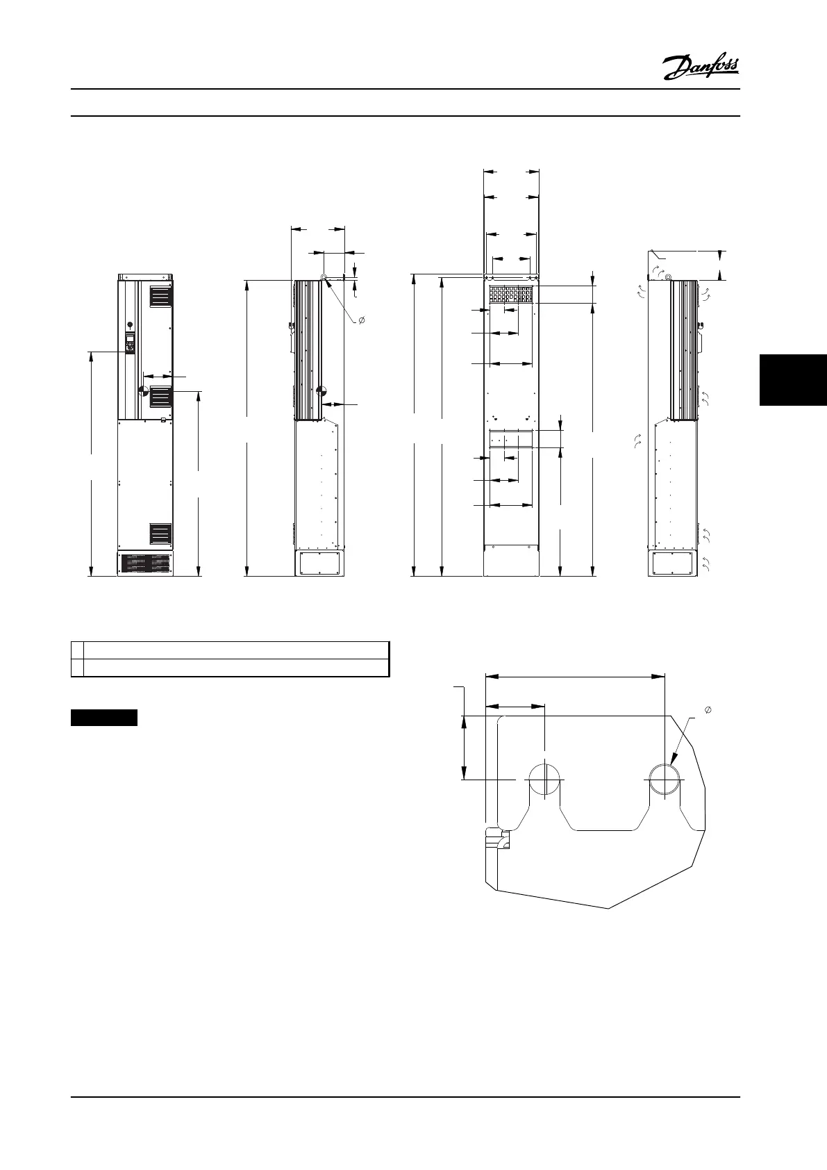
1
130BD466.10
2
Figure 6.21 Mechanical Dimensions, D8h
1
Ceiling
2 Air space outlet minimum 225 mm [8.9 in]
Table 6.14 Legend to Figure 6.21
NOTICE!
If using a kit to direct the airflow from the heatsink to
the outside vent on the back of the adjustable frequency
drive, the required ceiling clearance is 4 in [100 mm].
70
[2.8]
25
[1.0]
23
[0.9]
11
[0.4]
4X
130BD521.10
Figure 6.22 Top Mounting Hole Dimension Detail, D8h
Mechanical Installation Design Guide
MG34S222 Danfoss A/S © Rev. 2014-02-10 All rights reserved. 119
6 6
 Loading...


