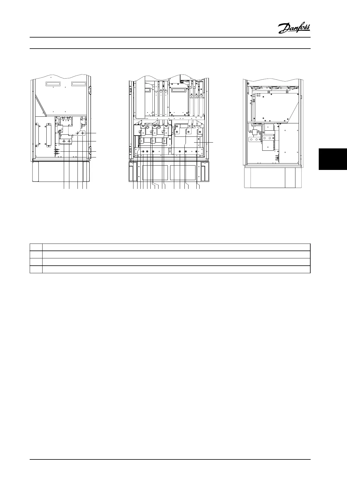
Terminal Locations - Rectifier (F10, F11, F12 and F13)
4
3
239.6 [ 9.43 ]
0.0 [ 0.00 ]
0.0 [ 0.00 ]
160.0 [ 6.30 ]
56.6 [ 2.23 ]
39.8 [ 1.57 ]
91.8 [ 3.61 ]
174.1 [ 6.85 ]
226.1 [ 8.90 ]
130BB534.11
R2/L12
R1/L11
91-1
91
S2/L22
S1/L21
92-1
T2/L32 93-1
92
T1/L31 93
U/T1 96 V/T2 97 W/T3 98
0.0 [ 0.00 ]
57.6 [ 2.27 ]
74.0 [ 2.91 ]
100.4 [ 3.95 ]
139.4 [ 5.49 ]
172.6 [ 6.80 ]
189.0 [ 7.44 ]
199.4 [ 7.85 ]
287.6 [ 11.32 ]
304.0 [ 11.97 ]
407.3 [ 16.04 ]
464.4 [ 18.28 ]
522.3 [ 20.56 ]
524.4 [ 20.65 ]
629.7 [ 24.79 ]
637.3 [ 25.09 ]
1 2
Figure 6.77 Terminal Locations - Rectifier. Connector Plate is 1.65 in [42 mm] below .0 Level.
1
Left Side View
2 Front View
3 Right Side View
4 Ground Bar
Table 6.44 Legend to Figure 6.77
Mechanical Installation Design Guide
MG34S222 Danfoss A/S © Rev. 2014-02-10 All rights reserved. 161
6 6

 Loading...


