EasyManuals Logo
Home>Danfoss>DC Drives>VLT AutomationDrive FC 300

Danfoss VLT AutomationDrive FC 300 Design Guide

Danfoss VLT AutomationDrive FC 300
296 pages
To Next Page IconTo Next Page
To Previous Page IconTo Previous Page
Page #186 background imageLoading...
Page #186 background image
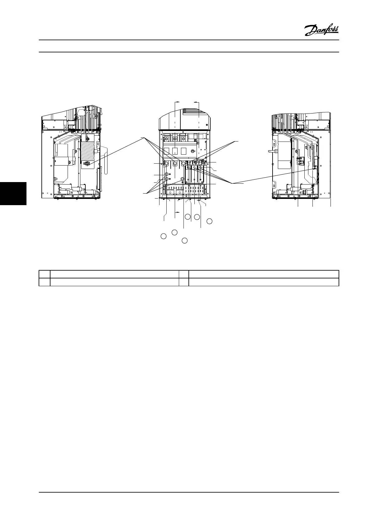
Terminal Locations - D5h
Take the following position of the terminals into consideration when designing the cable access.
B
B
A
A
45
1.8[ ]
0
0[ ]
46
1.8[ ]
99
3.9[ ]
153
6[ ]
146
5.8[ ]
182
7.2[ ]
193
7.6[ ]
249
9.8[ ]
221
8.7[ ]
260
10.2[ ]
118
4.6[ ]
0
0[ ]
148
5.8[ ]
221
8.7[ ]
90
3.6[ ]
196
7.7[ ]
227
9[ ]
113
4.4[ ]
0
0[ ]
206
8.1[ ]
A-A
R
S
T
U
V
W
B-B
130BC535.11
1
2
3
4
Figure 7.7 Terminal Locations, D5h with Disconnect Option
1
Line Power Terminals 3 Motor Terminals
2 Brake Terminals 4 Ground Terminals
Table 7.5 Legend to Figure 7.7
Electrical Installation Design Guide
184 Danfoss A/S © Rev. 2014-02-10 All rights reserved. MG34S222
77

Table of Contents

Other manuals for Danfoss VLT AutomationDrive FC 300

Questions and Answers:

Question and Answer IconNeed help?

Do you have a question about the Danfoss VLT AutomationDrive FC 300 and is the answer not in the manual?

Danfoss VLT AutomationDrive FC 300 Specifications

General IconGeneral
BrandDanfoss
ModelVLT AutomationDrive FC 300
CategoryDC Drives
LanguageEnglish

Related product manuals