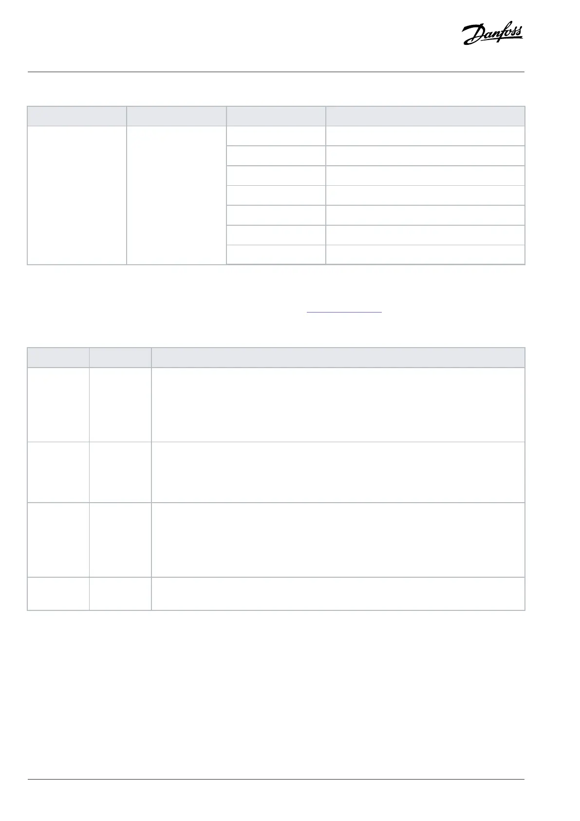
Table 48: Subfunction Code of Function Code 8
Function Function code Subfunction code Subfunction
1 Restart communication.
2 Return diagnostic register.
10 Clear counters and diagnostic register.
11 Return bus message count.
12 Return bus communication error count.
13 Return follower error count.
Diagnostics 8
14 Return follower message count.
9.8.11 Modbus Exception Codes
For a full explanation of the structure of an exception code response, refer to 9.8.5 Function Field.
Table 49: Modbus Exception Codes
Code Name Meaning
1 Illegal func-
tion
The function code received in the query is not an allowable action for the server (or follower). This
may be because the function code is only applicable to newer devices and was not implemented in
the unit selected. It could also indicate that the server (or follower) is in the wrong state to process
a request of this type, for example because it is not configured and is being asked to return register
values.
2 Illegal data
address
The data address received in the query is not an allowable address for the server (or follower). More
specifically, the combination of reference number and transfer length is invalid. For a controller
with 100 registers, a request with offset 96 and length 4 succeeds, while a request with offset 96
and length 5 generates exception 02.
3 Illegal data
value
A value contained in the query data field is not an allowable value for server (or follower). This indi-
cates a fault in the structure of the remainder of a complex request, such as that the implied length
is incorrect. It does NOT mean that a data item submitted for storage in a register has a value out-
side the expectation of the application program, since the Modbus protocol is unaware of the sig-
nificance of any value of any register.
4 Follower de-
vice failure
An unrecoverable error occurred while the server (or follower) was attempting to perform the re-
quested action.
9.9 How to Access Parameters
9.9.1 Parameter Handling
The PNU (parameter number) is translated from the register address contained in the Modbus read or write message. The parameter
number is translated to Modbus as (10 x parameter number) decimal. Example: Reading parameter 3-12 Catch up/slow Down Value (16
bit): The holding register 3120 holds the values of the parameters. A value of 1352 (decimal) means that the parameter is set to 12.52%.
Reading parameter 3-14 Preset Relative Reference (32 bit): The holding registers 3410 and 3411 hold the parameters’ values. A value of
11300 (decimal) means that the parameter is set to 1113.00.
106 | Danfoss A/S © 2024.01 AJ435824192086en-000101 / 130R1295
Design Guide | VLT® AutomationDrive FC 360

 Loading...


