Design Guide | VLT® AutomationDrive FC 360
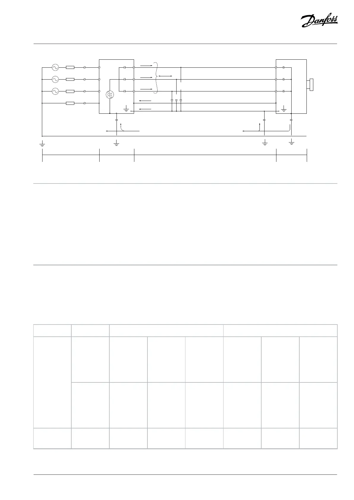
Figure 33: Electric Model Showing Possible Leakage Currents
1 Ground wire 2 Shield
3 AC mains supply 4 Drive
5 Shielded motor cable 6 Motor
Cs Possible shunt parasitic capacitance paths (varies with
different installations).
I
1
Common-mode leakage current
I
2
Shielded motor cable I
3
Safety ground (4th conductor in motor cables)
I
4
Unintended common-mode current
7.13.2 EMC Test Results
The following test results have been obtained using a drive (with options if relevant), a shielded control cable, a control box with
potentiometer, a motor, and motor shielded cable.
Table 18: EMC Test Results (Emission)
RFI filter type Conducted emission Radiated emission
EN 55011 Class B
Housing,
trades, and
light indus-
tries
Class A
group 1
Industrial en-
vironment
Class A
group 2
Industrial en-
vironment
Class B
Housing,
trades, and
light indus-
tries
Class A
group 1
Industrial en-
vironment
Class A
group 2
Industrial en-
vironment
Standards
and require-
ments
EN/IEC
61800-3
Category C1
Residential,
commercial,
or light indus-
trial
Category C2
Commercial,
or light indus-
trial
Category C3
Industrial
Category C1
Residential,
commercial,
or light indus-
trial
Category C2
Commercial,
or light indus-
trial
Category C3
Industrial
FC 360 90–315 kW
380–480 V
No No 150 m (492 ft) No No Yes
Danfoss A/S © 2024.01 AJ435824192086en-000101 / 130R1295 | 67

 Loading...


