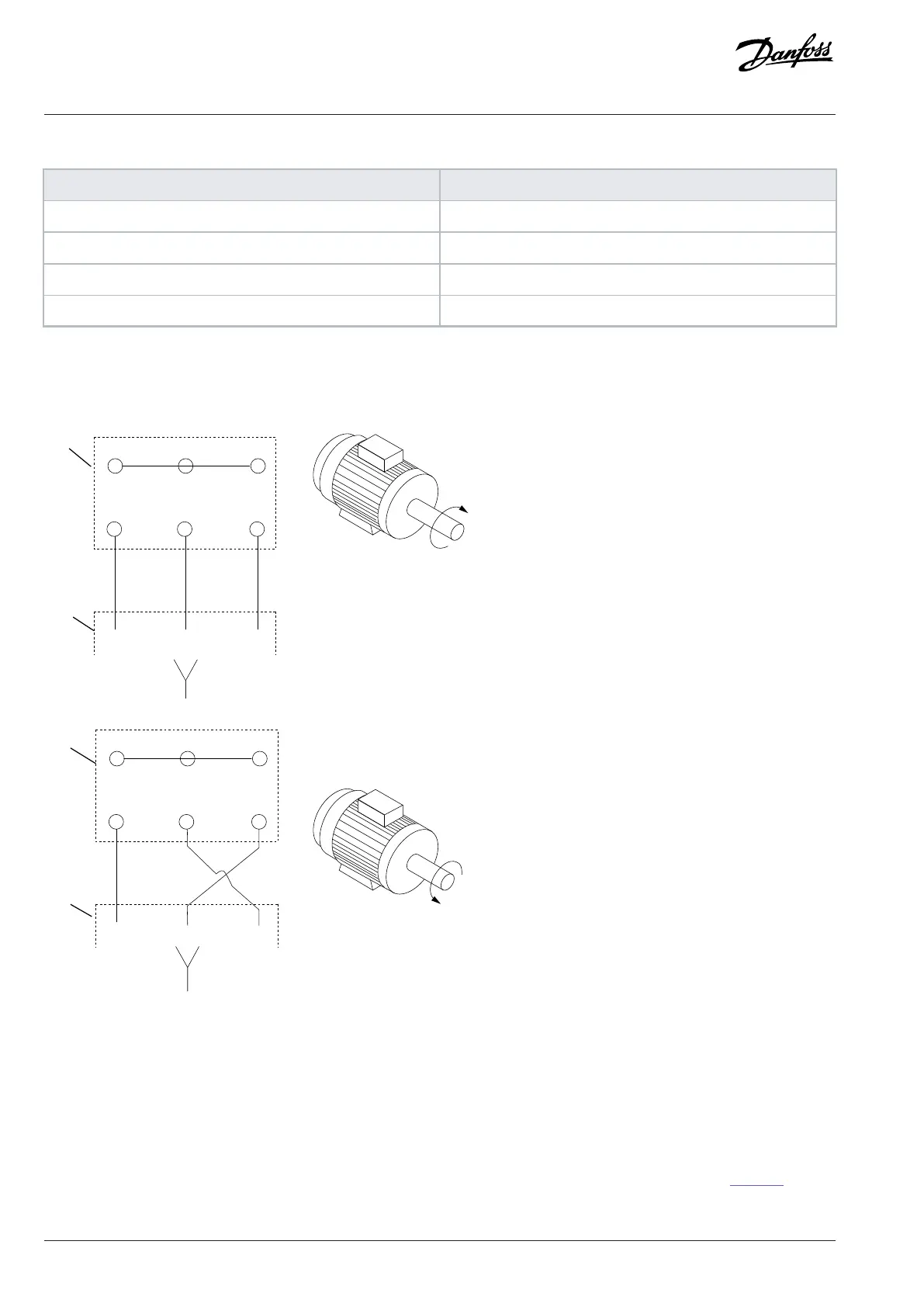
Table 13: Motor Cable Terminals Providing Clockwise Rotation (Factory Default)
Terminal Function
96 U/T1
97 V/T2
98 W/T3
99 Ground
The direction of rotation can be changed by switching 2 phases in the motor cable, or by changing the setting of parameter 4-10 Motor
Speed Direction.
Figure 26: Changing Motor Rotation
7.6.2 Motor Thermal Protection
The electronic thermal relay in the drive has received approval for single motor overload protection, when parameter 1-90 Motor
Thermal Protection is set for ETR Trip and parameter 1-24 Motor Current is set to the rated motor current (see the motor nameplate).
7.6.3 Parallel Connection of Motors
The drive can control several parallel-connected motors. For different configurations of parallel-connected motors, see Figure 27.
58 | Danfoss A/S © 2024.01 AJ435824192086en-000101 / 130R1295
Design Guide | VLT® AutomationDrive FC 360

 Loading...


