10 Application Examples
10.1 Introduction
The examples in this section are intended as a quick reference for common applications.
l Parameter settings are the regional default values unless otherwise indicated (selected in parameter 0-03 Regional Settings).
l Parameters associated with the terminals and their settings are shown next to the drawings.
l Required switch settings for analog terminals 53 or 54 are also shown.
10.2 AMA
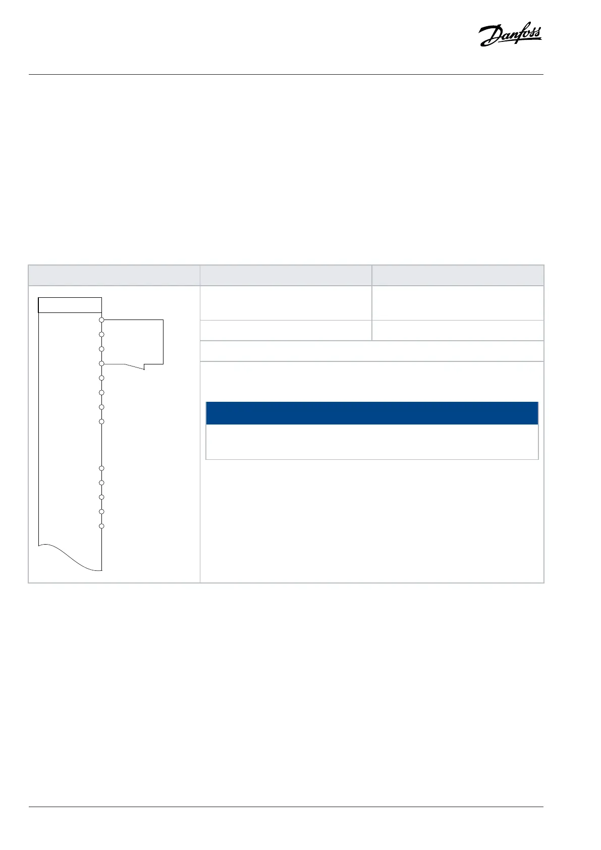
Table 66: AMA with T27 Connected
Parameter function Parameter setting
Parameter 1-29 Automatic Motor
Adaptation (AMA)
[1] Enable complete AMA
Parameter 5-12 Terminal 27 Digital Input *[2] Coast inverse
*=Default value
Notes/comments: Set parameter group 1-2* Motor Data according to motor
specifications.
NOTICE
If terminals 12 and 27 are not connected, set parameter 5-12 Terminal 27 Digital
Input to [0] No operation.
120 | Danfoss A/S © 2024.01 AJ435824192086en-000101 / 130R1295
Design Guide | VLT® AutomationDrive FC 360

 Loading...


