Table 8: Motor Cable Connection
96 97 98 99 Description
U V W PE
1)(1)
Motor voltage 0–100% of mains voltage. 3 wires out of motor.
U1 V1 W1 PE
(1)
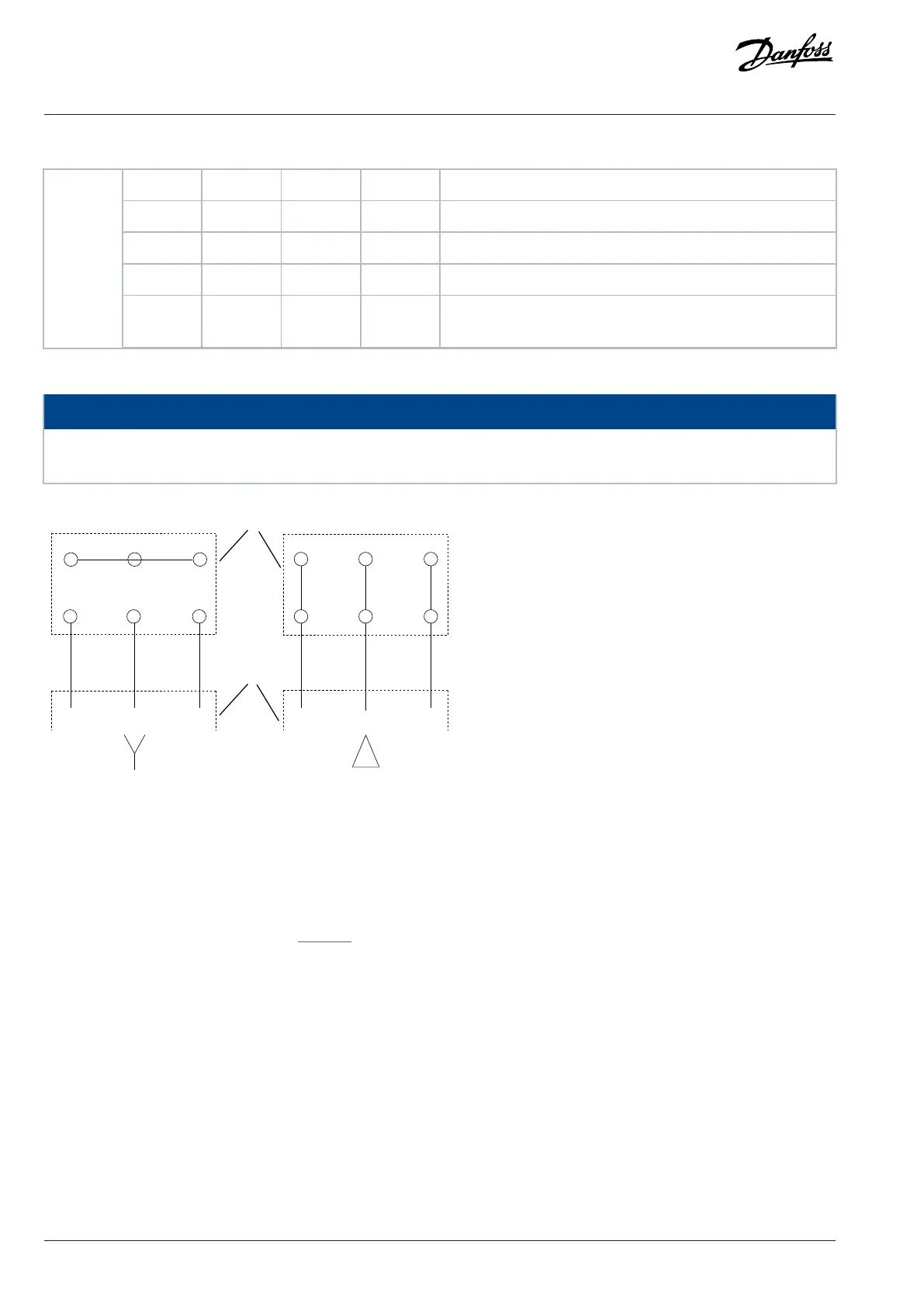
Delta-connected.
W2 U2 V2 PE
(1)
6 wires out of motor.
Terminal
U1 V1 W1 PE
(1)
Star-connected U2, V2, W2. U2, V2, and W2 to be interconnected
separately.
1) Protected ground connection.
NOTICE
In motors without phase insulation, paper, or other insulation reinforcement suitable for operation with voltage supply, use a sine-
wave filter on the output of the drive.
Figure 22: Motor Cable Connection
7.4 Control Wiring and Terminals
7.4.1 Correct Grounding of Control Cables
Control cables must be shielded and the shield must be connected with a cable clamp at both ends to the metal cabinet of the unit.
For correct grounding of control cables, see Figure 23.
52 | Danfoss A/S © 2024.01 AJ435824192086en-000101 / 130R1295
Design Guide | VLT® AutomationDrive FC 360

 Loading...


