The voltage distortion on the mains supply voltage depends on the size of the harmonic currents multiplied by the mains impedance for
the frequency in question. The total voltage distortion (THDi) is calculated based on the individual voltage harmonics using this formula:
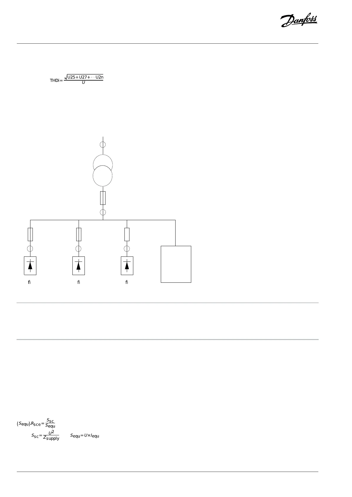
7.14.3 Effect of Harmonics in a Power Distribution System
In the following illustration, a transformer is connected on the primary side to a point of common coupling PCC1, on the medium voltage
supply. The transformer has an impedance Z
xfr
and feeds several loads. The point of common coupling where all loads are connected is
PCC2. Each load connects through cables that have an impedance Z
1
, Z
2
, Z
3
.
t i e r 2 R e c t i e r 3
O t h e r
L o a d s
x f r
Figure 36: Small Distribution System
PCC Point of common coupling MV Medium voltage
LV Low voltage Z
xfr
Transformer impedance
Z
#
Modeling resistance and inductance in the wiring
Harmonic currents drawn by non-linear loads cause distortion of the voltage because of the voltage drop on the impedances of the
distribution system. Higher impedances result in higher levels of voltage distortion.
Current distortion relates to apparatus performance and it relates to the individual load. Voltage distortion relates to system
performance. It is not possible to determine the voltage distortion in the PCC knowing only the harmonic performance of the load. To
predict the distortion in the PCC, the configuration of the distribution system and relevant impedances must be known.
A commonly used term for describing the impedance of a grid is the short circuit ratio R
sce
, where R
sce
is defined as the ratio between the
short circuit apparent power of the supply at the PCC (S
sc
) and the rated apparent power of the load.
where and .
Negative effects of harmonics
l Harmonic currents contribute to system losses (in cabling and transformer).
74 | Danfoss A/S © 2024.01 AJ435824192086en-000101 / 130R1295
Design Guide | VLT® AutomationDrive FC 360

 Loading...


