The torque control function is used in applications where the torque on the motor output shaft is controlling the application as tension
control. Torque control can be either in VVV+ torque open loop in flux sensorless or in flux control closed loop. The best performance
is with flux closed loop, especially near 0 speed. Torque control can be selected in parameter 1-00 Configuration Mode. Torque setting
is done by setting an analog, digital, or bus controlled reference. When running torque control, it is recommended to run a full AMA
procedure, because correct motor data is important in achieving optimal performance.
l Closed loop in VVC+ mode. This function is used in applications with low to medium dynamic variation of shaft, and offers excellent
performance in all 4 quadrants and at all motor speeds. The speed feedback signal is mandatory. It is recommended to use MCB102
option card. Ensure that the encoder resolution is at least 1024 PPR, and the shield cable of the encoder is well grounded, because
the accuracy of the speed feedback signal is important. Tune parameter 7-06 Speed PID Lowpass Filter Time to get the best speed
feedback signal.
l Open loop in VVC+ mode. The function is used in mechanically robust applications, but the accuracy is limited. The open-loop
torque function works for 2 directions. The torque is calculated based on the internal current measurement in the drive.
Speed/torque reference
The reference to these controls can be either a single reference or the sum of various references including relatively scaled references.
Handling of reference is explained in detail in the chapter Reference Handling.
8.3.4 Control Processing
8.3.4.1 Control Structure in VVC+
1 source
P 7-22 Process feedback
P 7-00 Speed PID
feedback source
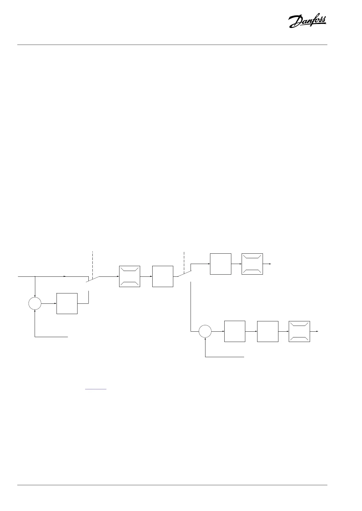
Figure 46: Control Structure in VVC+ Open-loop Configurations and Closed-loop Configurations
In the configuration shown in Figure 46, parameter 1-01 Motor Control Principle is set to [1] VVC+ and parameter 1-00 Configuration
Mode is set to [0] Speed open loop. The resulting reference from the reference handling system is received and fed through the ramp
limitation and speed limitation before being sent to the motor control. The output of the motor control is then limited by the maximum
frequency limit.
If parameter 1-00 Configuration Mode is set to [1] Speed closed loop, the resulting reference is passed from the ramp limitation and
speed limitation into a Speed PID control. The Speed PID control parameters are in parameter group 7-0* Speed PID Ctrl. The resulting
reference from the Speed PID control is sent to the motor control limited by the frequency limit.
86 | Danfoss A/S © 2024.01 AJ435824192086en-000101 / 130R1295
Design Guide | VLT® AutomationDrive FC 360

 Loading...


