Bus references are scaled according to the following rules:
l When parameter 3-00 Reference Range is set to [0] Min–Max, 0% reference equals minimum reference, and 100% reference equals
maximum reference.
l When parameter 3-00 Reference Range is set to [1] -Max–+Max, -100% reference equals -maximum reference, and 100% reference
equals maximum reference.
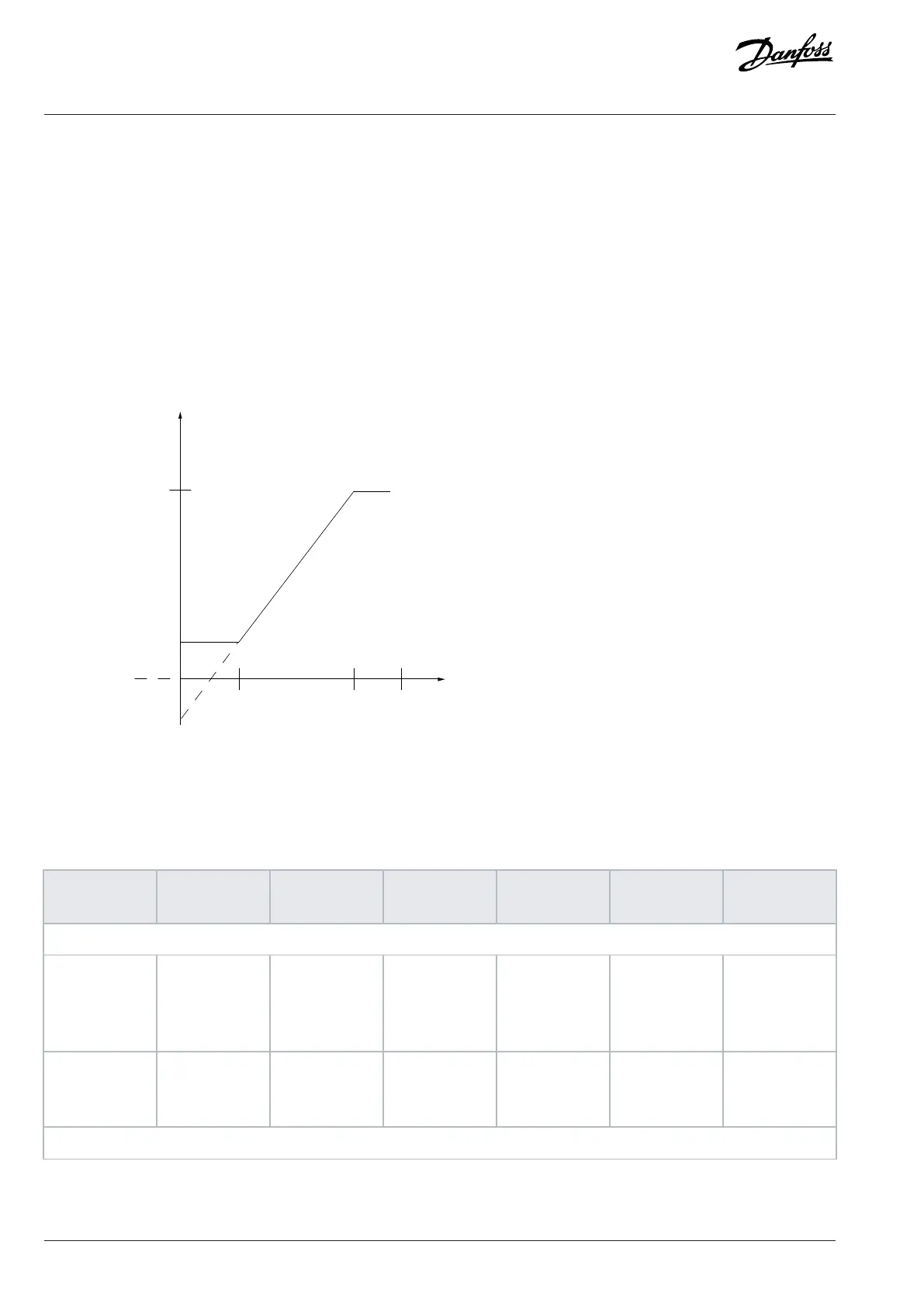
8.3.2.4 Scaling of Analog and Pulse References and Feedback
References and feedback are scaled from analog and pulse inputs in the same way. The only difference is that a reference above or below
the specified minimum and maximum endpoints (P1 and P2 in the following illustration) are clamped while a feedback above or below is
not.
Resource input
Terminal X
high
High reference/
feedback value
Low reference/
feedback value
Figure 42: Minimum and Maximum Endpoints
The endpoints P1 and P2 are defined in the following table depending on choice of input.
Table 28: P1 and P2 Endpoints
Input Analog 53
voltage mode
Analog 53
current mode
Analog 54
voltage mode
Analog 54
current mode
Pulse input 29 Pulse input 33
P1=(Minimum input value, minimum reference value)
Minimum refer-
ence value
Parameter 6-14
Terminal 53
Low Ref./Feedb.
Value
Parameter 6-14
Terminal 53
Low Ref./Feedb.
Value
Parameter 6-24
Terminal 54
Low Ref./Feedb.
Value
Parameter 6-24
Terminal 54
Low Ref./Feedb.
Value
Parameter 5-52
Term. 29 Low
Ref./Feedb.
Value
Parameter 5-57
Terminal 33
Low Ref./Feedb.
Value
Minimum input
value
Parameter 6-10
Terminal 53 Low
Voltage [V]
Parameter 6-12
Terminal 53 Low
Current [mA]
Parameter 6-20
Terminal 54 Low
Voltage [V]
Parameter 6-22
Terminal 54 Low
Current [mA]
Parameter 5-50
Terminal 29 Low
Frequency [Hz]
Parameter 5-55
Terminal 33 Low
Frequency [Hz]
P2=(Maximum input value, maximum reference value)
82 | Danfoss A/S © 2024.01 AJ435824192086en-000101 / 130R1295
Design Guide | VLT® AutomationDrive FC 360

 Loading...


