Design Guide | VLT® AutomationDrive FC 360
10.8 Encoder Direction
The order in which the pulses enter the drive determines the direction of the encoder.
l Clockwise direction means that channel A is 90 electrical degrees before channel B.
l Counterclockwise direction means that channel B is 90 electrical degrees before A.
The direction is determined by looking into the shaft end.
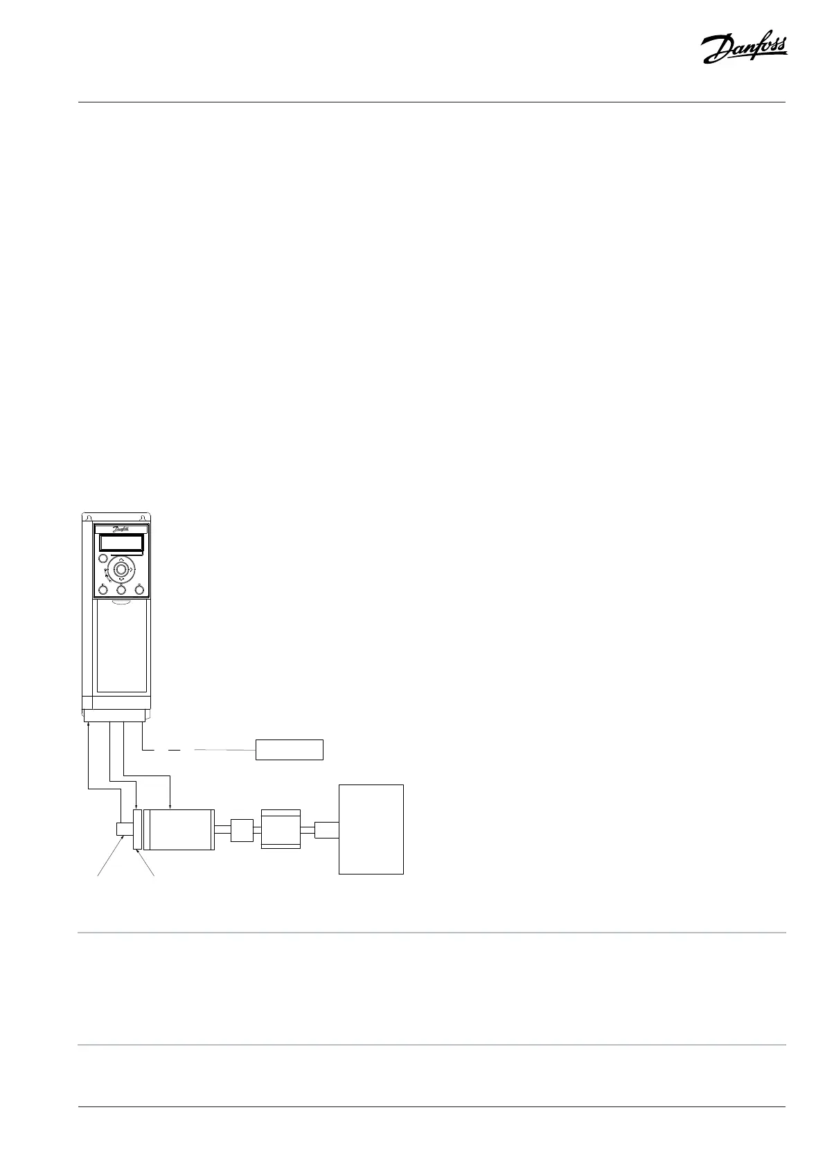
10.9 Closed-loop Drive System
A drive system usually consists of more elements such as:
l Motor.
l Brake (gearbox, mechanical brake).
l Drive.
l Encoder as feedback system.
l Brake resistor for dynamic brake.
l Transmission.
l Load.
Applications demanding mechanical brake control usually need a brake resistor.
Figure 68: Basic Setup for Closed-loop Speed Control
1 Brake resistor 2 Encoder
3 Mechanical brake 4 Motor
5 Transmission 6 Gearbox
7 Load
Danfoss A/S © 2024.01 AJ435824192086en-000101 / 130R1295 | 129

 Loading...


