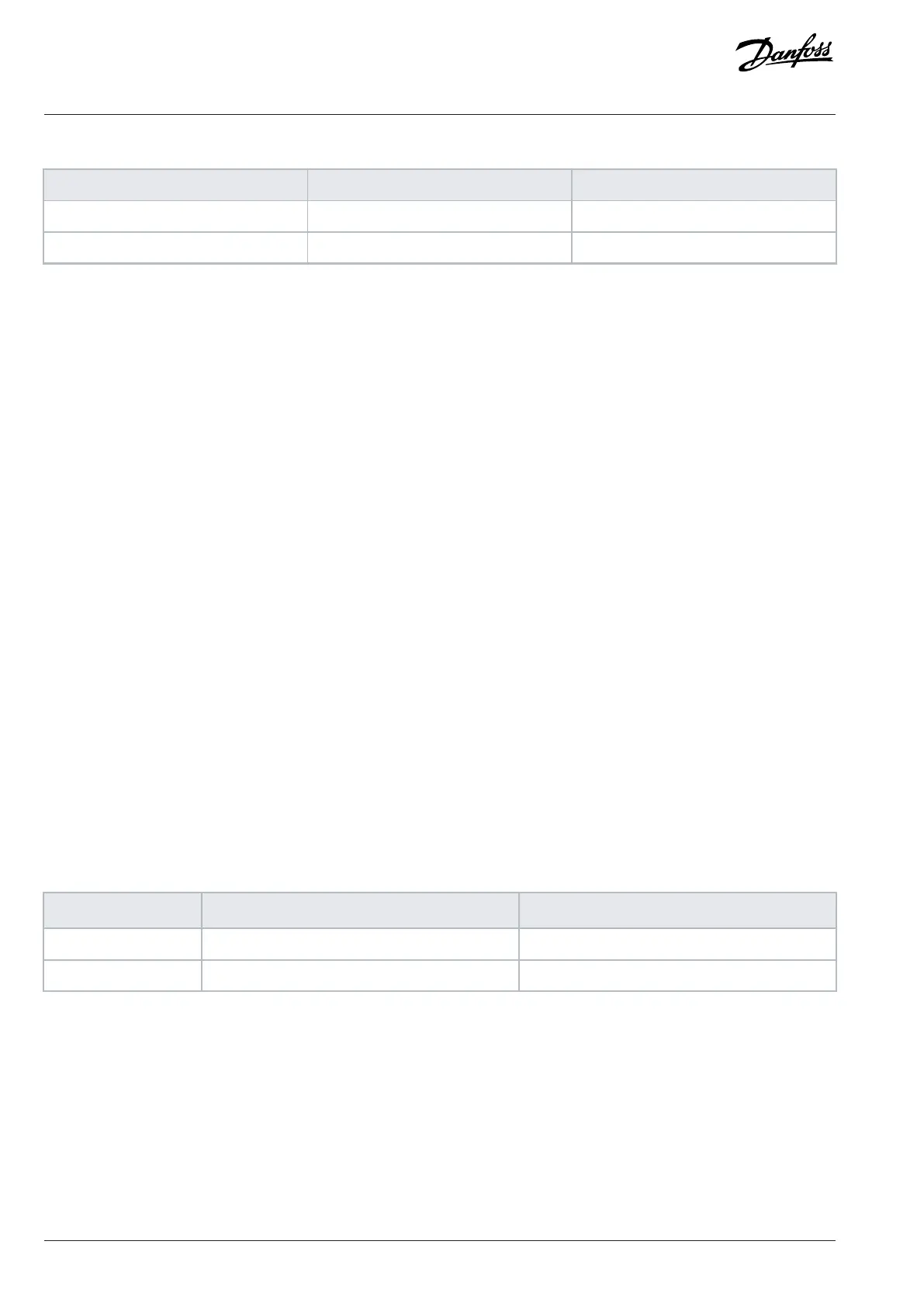
Table 5: Mounting Configurations
Enclosure size Wall/cabinet mount Pedestal mount (Standalone)
J8 X
1)(1)
–
J9 X
(1)
–
1) Can be wall-mounted, but Danfoss recommends that the drive is panel-mounted inside an enclosure due to its protection rating.
Mounting considerations:
l Locate the unit as near to the motor as possible. See the chapter Cable Lengths and Cross-sections for the maximum motor cable
length.
l Ensure unit stability by mounting the unit to a solid surface.
l Ensure that the strength of the mounting location supports the unit weight.
l Ensure that there is enough space around the unit for proper cooling. Refer to the chapter Back Channel Cooling.
l Ensure enough access to open the door.
l Ensure cable entry from the bottom.
6.5 Cooling
l Ensure that top and bottom clearance for air cooling is provided. Clearance requirement: 225 mm (9 in).
l Provide sufficient airflow flow rate. See the following table.
l Consider derating for temperatures starting between 45 °C (113 °F) and 50 °C (122 °F) and elevation 1000 m (3300 ft) above sea level.
See the chapter Derating for detailed information on derating.
The drive utilizes a back-channel cooling concept that removes heat sink cooling air. The heat sink cooling air carries approximately 90%
of the heat out of the back channel of the drive. Redirect the back-channel air from the panel or room by using:
l Duct cooling
Back-channel cooling kits are available to direct the heat sink cooling air out of the panel when IP20/Chassis drives are installed in
Rittal enclosures. Use of these kits reduces the heat in the panel and smaller door fans can be specified.
l Back-wall cooling
Installing top and base covers to the unit allows the back-channel cooling air to be ventilated out of the room.
Secure the necessary airflow over the heat sink.
Table 6: J8–J9 Airflow Rate
Enclosure size
Door fan/top fan [m
3
/hr (cfm)] Heat sink fan [m
3
/hr (cfm)]
J8 102 (60) 420 (250)
J9 204 (120) 840 (500)
6.6 Derating
6.6.1 Overview of Derating
Derating is a method used to reduce output current to avoid tripping the drive when high temperatures are reached within the
enclosure. If certain extreme operating conditions are expected, a higher-powered drive can be selected to eliminate the need for
derating. This is called manual derating. Otherwise, the drive automatically derates the output current to eliminate the excessive heat
generated by extreme conditions.
46 | Danfoss A/S © 2024.01 AJ435824192086en-000101 / 130R1295
Design Guide | VLT® AutomationDrive FC 360

 Loading...


