1 Control cables and serial communication cables must be
fitted with cable clamps at both ends to ensure the best
possible electrical contact.
2 Do not use twisted cable ends (pigtails). They increase the
shield impedance at high frequencies.
3 If the ground potential between the drive and the PLC is
different, electric noise can occur that disturbs the entire
system. Fit an equalizing cable next to the control cable.
Minimum cable cross-section: 16 mm
2
(6 AWG).
4 If long control cables are used, 50/60 Hz ground loops are
possible. Connect 1 end of the shield to ground via a 100
nF capacitor (keeping leads short).
5 When using cables for serial communication, eliminate
low-frequency noise currents between 2 drives by
connecting 1 end of the shield to terminal 61. This terminal
is connected to ground via an internal RC link. Use twisted-
pair cables for reducing the differential mode interference
between the conductors.
7.4.2 Control Cable Routing
Tie down and route all control wires. Remember to connect the shields in a proper way to ensure optimum electrical immunity.
l Isolate control wiring from high-power cables.
l When the drive is connected to a thermistor, ensure that the thermistor control wiring is shielded and reinforced/double insulated. A
24 V DC supply voltage is recommended.
Fieldbus connection
Connections are made to the relevant options on the control card. See the relevant fieldbus instruction. The cable must be tied down
and routed along with other control wires inside the unit.
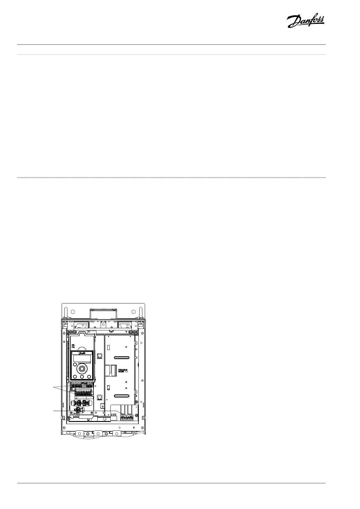
7.4.3 Control Terminals
Figure 24: Control Terminal Locations
54 | Danfoss A/S © 2024.01 AJ435824192086en-000101 / 130R1295
Design Guide | VLT® AutomationDrive FC 360

 Loading...


